Time to do some reading on the basics of quarter wave enclosures
never seen one with such an extreme taper and usually the driver is at the start of the line
Clive,
MDF is not a recommended build material. Use quality plywood. With a driver as large as the Morel intended, 15mm might do (it would if you had a pair loaded push-push). 18mm plywood would probably be recommended for a single driver.
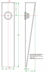
Here is a sketch of what Paul specified. It would normally be folded once to create a useful package.

dave
MDF is not a recommended build material. Use quality plywood. With a driver as large as the Morel intended, 15mm might do (it would if you had a pair loaded push-push). 18mm plywood would probably be recommended for a single driver.
24:1
Here is a sketch of what Paul specified. It would normally be folded once to create a useful package.
dave
Attachments
never seen one with such an extreme taper and usually the driver is at the start of the line
The taper is severe, but that makes it more compact. Paul is well known for his heavily tapered lines. Since the advent of proper TL-modelers, an end-loaded driver is rarely seen.
dave
To any of you concerned about my use of "severe" tapers, I'd much prefer they to be called aggressive because there's nothing about the modeled or sonic results that's at all severe. I never use a taper less than 10:1, simply because of its attributes of making the line a lot shorter and, more important, smoothing out the ripples in the response like more stuffing would do but without sacrificing low-end output. I've used a taper ratio of 16:1 and 25:1 quite effectively in personal builds. The only way an aggressive taper can be problematic is if the air velocity in the end of the line becomes excessive and I always make sure that is not an issue (17 m/s or less) when the driver is driven to Xmax and a bit beyond at a frequency that is likely to be part of the musical content.
Paul
Paul
your insert image is asking for a URL
You also have the choice of uploading a file from your computer.
dace

")
Frankly, designing a line with its area sized as a percentage of Sd has no real meaning, and certainly not a requirement. Assuming you have decent modeling software, like Martin King's, I just start out with a line width equal to or slightly greater than the driver's flange diameter, and often an arbitrary line depth, start usually with a taper of 10:1, which then sets the line's area dimensions at the other end, the same width and 1/10 of the depth. But, before I start all that, I calculate the line's required length based on its desired 1/4-wavelength resonant frequency as if the line will not be tapered, then multiply that length by 0.6 to determine the length of the 10:1 tapered line. All of these dimensions, line length, width, etc, can be manipulated during modeling to achieve the desired results.
Paul
Paul
Paul what is a taper ratio of 24:1
Can you rather put it as a percentage of the Sd at the start of the line and a percentage of the Sd at the end of the line
As you are now aware, Dave's drawing in Post #24 illustrates quite nicely what I modeled, but you would build it folded once for practicality.
Paul
Paul
Paul, when you say the woofer centre is 16 inches from the beiginning of the line do you mean there is a box that is 16 inches long and does not count as part of the line length
here is a question ? does the baffle step diffraction get influenced by the material used in the baffle
So for instance 12mm mdf vs 25 mm concrete as extreme examples Will the concrete exibit this to a much lower extent?
Speaker design is not as simple as ABC then
thanks again to everyone for the effort in replying
Clive
my buttons above the text box are
remove text formatting , bold , italics , underscore , colour , insert link , insert image ( which pops up a box asking for URL only) and wrap
Oh got it now go advanced does the trick !!!!
so that does it then the shape is settled now I just have to work out how to wrap this TL around around a concrete molded mid-range either it will look really sexy or damn ugly
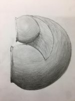
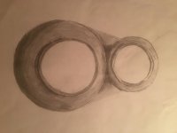
I like the idea of concrete about 5 months ago I drew this up as an idea to mold speakers in concrete , Now this is what I called sexxxxy but I wont argue with anyone who insists on ugly
remove text formatting , bold , italics , underscore , colour , insert link , insert image ( which pops up a box asking for URL only) and wrap
Oh got it now go advanced does the trick !!!!
The taper is aggressive, but that makes it more compact. Paul is well known for his heavily tapered lines. Since the advent of proper TL-modelers, an end-loaded driver is rarely seen
so that does it then the shape is settled now I just have to work out how to wrap this TL around around a concrete molded mid-range either it will look really sexy or damn ugly
I like the idea of concrete about 5 months ago I drew this up as an idea to mold speakers in concrete , Now this is what I called sexxxxy but I wont argue with anyone who insists on ugly
Attachments
...but you would build it folded once for practicality.
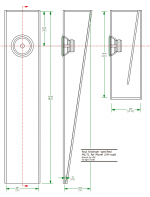
As i mentioned as well. Here is a 1st pass folding added. Do note that i rationalized the dimensions to metric and this drawn with 18mm material.
Given the large size of the midrange, i would mount it on top with the tweeter below (if one rotates the top of the TL by 30° or so, one can reduce the mounted height of the tweeter & midrange)
dave
Attachments
- Home
- Loudspeakers
- Multi-Way
- Crossover frequency for transmission line