I have a transmission line(-ish) box designed for a Peerless 830883 in Leonard Audio Transmission Line. It requires about 0.5lb/ft^3 of stuffing before the response flattens out enough that it looks like something I would want to use though.
The box is not precisely a transmission line: it has a fairly large open volume behind the driver, followed by a tapered tube is quite a bit shorter than the intended quarter wave tuning.
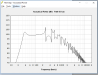
Because the box does not fit the precise definition of any particular type of enclosure I know of (would this qualify as a TH or BLH?), I wanted to validate this in another program. When I set up a similar enclosure in Hornresp, the peaks and nulls seem to show up right around the same frequencies as they do in LATL, they're just so tall that it doesn't look like a usable response. Is Hornresp able to simulate stuffing? It looks like it used to have an option to that's not there anymore. And anyway, who do I trust here?
The box is not precisely a transmission line: it has a fairly large open volume behind the driver, followed by a tapered tube is quite a bit shorter than the intended quarter wave tuning.
Because the box does not fit the precise definition of any particular type of enclosure I know of (would this qualify as a TH or BLH?), I wanted to validate this in another program. When I set up a similar enclosure in Hornresp, the peaks and nulls seem to show up right around the same frequencies as they do in LATL, they're just so tall that it doesn't look like a usable response. Is Hornresp able to simulate stuffing? It looks like it used to have an option to that's not there anymore. And anyway, who do I trust here?
Last edited:
Looks like MJKing of quarter-wave.com fame posted some measurement results of his empty vs. stuffed cabinets here: IMF Transmission Line Stuffing? | Audiokarma Home Audio Stereo Discussion Forums that would seem to agree with what Leonard Audio is telling me, so that's good.
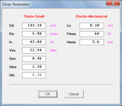
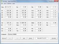
Something in this ballpark. Rms and Mmd aren't correct because they're not given directly in the spec sheet and I haven't backtracked through T-S formulas to figure out how to compute them.
Attachments
Rms and Mmd aren't correct because they're not given directly in the spec sheet and I haven't backtracked through T-S formulas to figure out how to compute them.
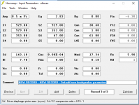
1. Double-click on the Sd input text box in Edit mode to enter driver Thiele-Small parameter values as shown in Attachment 1.
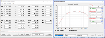
2. Resulting equivalent electro-mechanical driver parameter values should be as shown in Attachment 2.
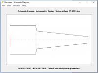
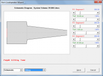
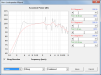
3. Select the Loudspeaker Wizard tool to add absorbent filling material as shown in Attachments 3 and 4.
You have specified radiation into eighth space (Ang = 0.5 x Pi) - is this what you want?
Attachments
Augsperger called a TL that had a large chamber at the beginning appended by a longer section with a constant but smaller area a Coupling Chamber design. If you taper that appended section, which I have done quite successfully, I'd still call it a coupling chamber design. George indicated the coupling chamber "should" contain about 1/3 of the total line volume, but my experience says it can be more, like 1/2.
Paul
Paul
From the description you have a saline — Augspurger has a more descriptive name, can’t recall it. Can you post a sketch?
dave
Awesome, thank you all, especially David for your contributions and help with hornresp. What you're showing in those attached images looks very close to what I was seeing in LATL, so that's encouraging. I'll try plugging those numbers in and playing around with it.
@planet10, yeah, I get that about the AudioKarma thread. It's kind of morbidly amusing to see someone just dig in deeper when the person they're accusing of fabricating ideas posts their own measurements that confirm their theories which in turn have been confirmed by someone else's master's or PhD thesis, as well as by others using their software. It seems pretty clear to me reading that thread who is participating in good faith and who is not.
@pkitt, thanks for the recommendation on Augsperger and coupling chambers. That looks like a rich topic to dig into. In the meantime, any designs of yours that you can share?
It looks like it would probably be hard to overstuff it. IIRC this design is up to 6-7dB louder than an equivalent sealed box around 40-50Hz, close to what we might expect for a bass reflex. It looks like even if I'm dropping that a few dB or more with overstuffing, I'm still doing better than I would with sealed, and with much lower excursion at the bottom end as well.
Looking forward to checking out Augsperger (http://diyaudioprojects.com/Technical/Papers/Loudspeakers-on-Damped-Pipes.pdf) in more detail seeing as his abstract says one of his alignments gets close to sealed box response with reduced excursion - basically what I'm going for. I'm crossing over to a sub, just looking for the lowest distortion design for my midbass, not necessarily loud.
Looking forward to checking out Augsperger (http://diyaudioprojects.com/Technical/Papers/Loudspeakers-on-Damped-Pipes.pdf) in more detail seeing as his abstract says one of his alignments gets close to sealed box response with reduced excursion - basically what I'm going for. I'm crossing over to a sub, just looking for the lowest distortion design for my midbass, not necessarily loud.
Attachments
Augsperger called a TL that had a large chamber at the beginning appended by a longer section with a constant but smaller area a Coupling Chamber design.
Is this similar? http://www.ejjordan.co.uk/PDFs/Eikona_VTL.pdf
Yes, that Jordan design is similar but suffers from a lumpy response and, I think, a too long line for the driver's fS and Qts; it's just not optimized for the driver.
Paul
Paul
Is this similar? http://www.ejjordan.co.uk/PDFs/Eikona_VTL.pdf
Stroll through Martin King's gallery at: Quarter Wavelength Loudspeaker Design Gallery and you will find photos of a number of my designs. If you're interested in any of them, send me a private message with your email address and I'll send you write-ups.
Paul
Paul
Awesome, thank you all, especially David for your contributions and help with hornresp. What you're showing in those attached images looks very close to what I was seeing in LATL, so that's encouraging. I'll try plugging those numbers in and playing around with it.
@planet10, yeah, I get that about the AudioKarma thread. It's kind of morbidly amusing to see someone just dig in deeper when the person they're accusing of fabricating ideas posts their own measurements that confirm their theories which in turn have been confirmed by someone else's master's or PhD thesis, as well as by others using their software. It seems pretty clear to me reading that thread who is participating in good faith and who is not.
@pkitt, thanks for the recommendation on Augsperger and coupling chambers. That looks like a rich topic to dig into. In the meantime, any designs of yours that you can share?
that Jordan design is similar but suffers from a lumpy response/QUOTE]
Sims Scott did in comparison to the GM ML-TLs.
dave
Attachments
ML-TL means mass-loaded transmission line. Specifically there's a port near the end of the line and the mass of air in that port loads the end of the line. More technically, the line in an ML-TL usually has a constant area along all or most of its length, and the 1/4-wavelength resonant frequency from the line's length is not low enough to completely tune the system optimally for the driver. The port, then completes the tuning. All TLs have stuffing, some have morethan others and some have less than others.
Paul
Paul
On the definition of MLTL: does MLTL just mean the same thing as "stuffed TL" or no?
- Status
- This old topic is closed. If you want to reopen this topic, contact a moderator using the "Report Post" button.
- Home
- Loudspeakers
- Multi-Way
- Validating LA transmission line box in Hornresp: how to simulate line stuffing?