Based on Augsperger's paper here: http://diyaudioprojects.com/Technical/Papers/Loudspeakers-on-Damped-Pipes.pdf, I might actually be able to make better use of just a coupling chamber with a straight pipe than what I've been proposing so far. He mentions in section 8.5:
"It is possible to combine various pipe geometries. As a case in point, a coupling chamber can drive a tapered pipe *[note: this is the design I [altie] have been talking about so far]*. Although it has been used in at least two commercial transmission-line designs, this combination provides no reduction in pipe volume and slightly degrades the low-frequency performance.
Other combinations are similarly disappointing. For example, a tapered pipe with an offset loudspeaker can be made to squeeze out another decibel of efficiency, but at the cost of greater cone excursion. The net result is a decrease in the maximum low-frequency output."
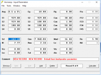
Back in Hornresp, I've got a different design taking up a much smaller volume (attached). The pass band here extends further, from nearly 40-300Hz.
It looks like that comes at the cost of a much stronger ripple. That could be OK, actually. I should mention more about the overall system design: this is going to be a heavily DSPed system anyway, so as long as stuffing is sufficient to take care of much higher-Q peaks of the ripples than the DSP would be prepared to handle, we're fine. The resulting design should be buildable without having to cut any funny angles into wood, perhaps using two 1.5" nominal PVC pipes for the line to improve turbulence over sharp bends and corners in a rectangular cross section wooden line.
According to LATL, this design also achieves a peak of 10dB over infinite baffle performance with low excursion at the bottom end of its pass band. So that's looking promising for the design goal of lowering distortion, I think.
"It is possible to combine various pipe geometries. As a case in point, a coupling chamber can drive a tapered pipe *[note: this is the design I [altie] have been talking about so far]*. Although it has been used in at least two commercial transmission-line designs, this combination provides no reduction in pipe volume and slightly degrades the low-frequency performance.
Other combinations are similarly disappointing. For example, a tapered pipe with an offset loudspeaker can be made to squeeze out another decibel of efficiency, but at the cost of greater cone excursion. The net result is a decrease in the maximum low-frequency output."
Back in Hornresp, I've got a different design taking up a much smaller volume (attached). The pass band here extends further, from nearly 40-300Hz.
It looks like that comes at the cost of a much stronger ripple. That could be OK, actually. I should mention more about the overall system design: this is going to be a heavily DSPed system anyway, so as long as stuffing is sufficient to take care of much higher-Q peaks of the ripples than the DSP would be prepared to handle, we're fine. The resulting design should be buildable without having to cut any funny angles into wood, perhaps using two 1.5" nominal PVC pipes for the line to improve turbulence over sharp bends and corners in a rectangular cross section wooden line.
According to LATL, this design also achieves a peak of 10dB over infinite baffle performance with low excursion at the bottom end of its pass band. So that's looking promising for the design goal of lowering distortion, I think.
Attachments
Last edited:
Also wondering about resources on port placement. I've got a couple designs forking off that can either use one or two 1.5" nominal diameter PVC pipes. That raises the further question of having those pipes contained within the enclosure, possibly venting out the front baffle.
A second option would be to have holes in the back baffle with the PVC pipes plugging into them externally, probably with a 90 degree elbow so they'd face upwards along the back baffle. That would save enclosure volume. It also might cause fewer issues with real box matching up to the simulations due to the PVC throat mating up with the coupling chamber closer to the chamber's simulated end than if the PVC was winding around inside the chamber itself.
A second option would be to have holes in the back baffle with the PVC pipes plugging into them externally, probably with a 90 degree elbow so they'd face upwards along the back baffle. That would save enclosure volume. It also might cause fewer issues with real box matching up to the simulations due to the PVC throat mating up with the coupling chamber closer to the chamber's simulated end than if the PVC was winding around inside the chamber itself.
- Status
- This old topic is closed. If you want to reopen this topic, contact a moderator using the "Report Post" button.