I can't quite make out the scale - is it in milliseconds?
If so, it appears that your design has minimized later significantly discrete reflections that will occur in a room with a point source by spreading the reflections across the time scale -> all the way to the initial impulse. A point source will have a period of dead calm following the initial impulse, which your plot does not show.
Which way is better is an open question. Love to test that some day.
Yes, it's milliseconds. I could have gotten a cleaner result with more damping. The missus does not agree with that though. For instance, there is no damping at all on the front wall behind the speakers.
This is as measured out in the room at the listening spot. It's a compromise made with the wife, I'm under strict rules not to add any more.
I agree with these last points, but it was sounding more and more like people were saying that comb filtering is not an issue - it can be a very substantial issue. What the ears do is very minimal compared to what a room does in this regard.
It sure is... I'd wish people would look at the room they are in to be able to make sense of what they really get to hear.
Even with more damping, what you get is what I would expect. The long line smears the impulse response of the source - just like the theory says it should - and this results in a smeared out room impulse response. I don't think that more damping would actually change it that much, it's a function of the source type.
As I said, I'd love to simulate this issue and test it. Create a line impulse response and a point one and ask people to resolve image locations or colorations given equal energy in the non-impulsing domain of say > .5 milliseconds
As I said, I'd love to simulate this issue and test it. Create a line impulse response and a point one and ask people to resolve image locations or colorations given equal energy in the non-impulsing domain of say > .5 milliseconds
Line array step response.
Measure right here, kuze array (32 x 2").
Bottom middle graph.
Kuze3201 Line Array | Parts Express Project Gallery
Measure right here, kuze array (32 x 2").
Bottom middle graph.
Kuze3201 Line Array | Parts Express Project Gallery
Showing the impulse response of any speaker system where you have applied a FIR filter is pointless. It doesn't matter if it is a floor to ceiling array or a conventional 2-way speaker system because if the FIR filter did it's job the resulting impulse response will be perfect... but only at the measurement position at which you designed the FIR filter. At some other listening position it could become even worse than if you didn't apply the FIR filter.
The real test of any speaker system is showing that it behaves well at many listening positions and not just some particular spot where you took 1 measurement and applied some form of optimised correction.
The point of a floor to ceiling array is that the linear distortion (frequency response, impulse response) without any type of FIR correction is theoretically better than a single speaker system in the same room. Theoretically with a floor to ceiling line array there are an infinite number of sources so room reflections from the floor and ceiling are eliminated -> there are an infinite number of combs which become infinitely small in amplitude -> flat. Obviously there are limitations because the roof and floor will absorb some of the sound instead of being perfect reflections and also for drivers which are circular there is some dead space between each driver. Additionally a vertical array doesn't do much to deal with reflections from the side walls - as a result of all this you will still get some amount of combing at the listening position.
The only other advantage of a vertical array is the sheer number of drivers lower non-linear distortion since each driver doesn't have to work nearly as hard to produce the same sound level as a single driver system. Other than that, an vertical array is just like any other speaker.
A corner floor to ceiling array can theoretically attempt to also use side wall reflections to it's advantage. Again this relies on the speaker drivers having an ideal power response which cannot be achieved perfectly in practice.
Hearing "Smearing" from multiple speakers is a myth. Humans are notoriously bad at hearing timing differences less than a few milliseconds. When the two sources arriving at slightly different times (<1ms) having the same frequency arrive at our ears, what we hear is a variation of amplitude (i.e. combing/lobing frequency response) due to constructive and destructive interference. For us to actually discern multiple sources at different positions requires signals having a broad range and frequencies and a huge difference in timing if they are playing the same content - tens of milliseconds.
CBT arrays and arrays which use power tapering are just ways of reducing the effects of combing without relying on the floor and/or roof reflections which require that the array extend to the floor and/or roof. This also means that they theoretically now suffer from the unwanted floor and/or roof reflections like any normal speaker design would.
Last edited:
Showing the impulse response of any speaker system where you have applied a FIR filter is pointless. It doesn't matter if it is a floor to ceiling array or a conventional 2-way speaker system because if the FIR filter did it's job the resulting impulse response will be perfect... but only at the measurement position at which you designed the FIR filter. At some other listening position it could become even worse than if you didn't apply the FIR filter.
Hammering the impulse into shape with a FIR filter is pointless, yes. However the IR I showed isn't that perfect. It was created with a frequency dependent window, I made sure it does hold up at other spots along the listening position. This is because the largest room anomalies were dealt with by absorbing the first reflections.
I've shown much more of how this was done in my thread, I've also played with using an average of multiple measurements along the listening area as a base for FIR filtering (summing the separate IR's into one average after aligning them in time) and use that as a base for filtering. In theory, the average of these multiple measurements would filter out the location specific room effects. Anyone interested enough can look it up.
The reason it works isn't because the IR was hammered into shape at one spot. I agree that would be a bad thing. But FIR filters in itself are not a bad thing if you don't use them to try to correct for very local room anomalies.
It's not what tool you use, it is how you use it. FIR software suites like Audiolense, Acourate and DRC-FIR give you full control over how to use it.
I often see lots of doubt about these FIR tools. The most common fear that it will get worse at other spots beside the measurement position. However we have shown before how, why and when it can and does work for more than one spot. Used with care and with the help of room treatment.
That's not tied to arrays specifically. There are other examples in this forum from mitchba showing his FIR correction of a 3-way with Acourate and how that holds up along a large area.
Last edited:
The point of a floor to ceiling array is that the linear distortion (frequency response, impulse response) without any type of FIR correction is theoretically better than a single speaker system in the same room. Theoretically with a floor to ceiling line array there are an infinite number of sources so room reflections from the floor and ceiling are eliminated -> there are an infinite number of combs which become infinitely small in amplitude -> flat. Obviously there are limitations because the roof and floor will absorb some of the sound instead of being perfect reflections and also for drivers which are circular there is some dead space between each driver. Additionally a vertical array doesn't do much to deal with reflections from the side walls - as a result of all this you will still get some amount of combing at the listening position.
The only other advantage of a vertical array is the sheer number of drivers lower non-linear distortion since each driver doesn't have to work nearly as hard to produce the same sound level as a single driver system. Other than that, an vertical array is just like any other speaker.
Not that different from what I said, as I mentioned that large vertical planes parallel to arrays are the things to watch out for. However due to the multiple sources a lot of other small things in the room get "averaged" out. Because the separate drivers all have their reflections at a slightly different timing...
This makes it possible to get good results in a living room with only a few places that need treatment. I do see their drop of only 3 dB for each doubling of distance as another advantage.
Pretty sure I've linked this thread before, but it does a good job of analysing the pro's of arrays: Infinite Line Source: analysis
For me, their small foot print, placement close to the wall and minor treatment needed (with planning) to get excellent results were the prime reasons to use them in my relatively small room.
CBT arrays and arrays which use power tapering are just ways of reducing the effects of combing without relying on the floor and/or roof reflections which require that the array extend to the floor and/or roof. This also means that they theoretically now suffer from the unwanted floor and/or roof reflections like any normal speaker design would.
CBT arrays use the floor reflection to virtually extend their shape. They also throw way less energy at the ceiling, so I don't agree that they will act the same as a normal speaker in regards to floor and ceiling reflections.
For a short (finite) array they are a very smart concept. Not as prone to parallel plane reflections as the straight array as their shape will partially help average out those reflections too. This means it would require even less room treatment, however they do need more space to set them up.
CBT arrays use the floor reflection to virtually extend their shape.
That's true for one implementation of a CBT. It's not a requirement that all CBTs do that.
")
True, however it wouldn't be fair to say the CBT concept does nothing positive with regards to floor and ceiling reflections.
Agreed.
Don't take my word for it, just try and figure out why I said what I did
Take a piece of paper and start to draw some lines...
I'm not denying driver spacing has an influence. But eventually it will be dependent on the distances of each of the drivers to your ear (or measurement point). Some drivers will sum, others will subtract... even if you use very small drivers. Closer driver spacing (and as a result there will be more of them) will make it a more gradual process. Much like anti-aliasing.
Look at this example that I typed out in another thread...
The comb filter pattern you get from an array at the listener's position will always be related to driver spacing and distance from that array and the (perceived) length of that array.
Where the combing starts (at what frequency) isn't as clear cut as just assuming it's the frequency based on quarter wave distance from center to center driver spacing. That's all I'm saying. That point where the combing starts to interfere in frequency will depend on more factors than driver spacing alone.
Take a focussed array, even though it has driver spacing it won't exhibit a combing pattern when you measure it in it's exact focus point. However, move out of that focus point and you'll see the comb patterns.
You seem to assume that sound waves from different drivers start to interact with each other after a few meters (at the listening position), which as far as I understand it, would be as soon as they meet each other (in this case just in front of the drivers) and the result of that is what we hear at the listening position.
Drivers do or don't couple (work together) at a certain frequency and location from each other; if not, they interfere with each other and you get an interference patern with peaks and dip which is combfiltering.
The listening position plays no part in this happening (with 1 speaker which has several drivers), but is on influence on how we perceive it. Vertical combfiltering is a lot less noticable for us a our ears and ear canals are positioned horizontally.
If the drivers would be left and right of the listening position, as in the left and right speaker there will always be interference between them. Once they are more then 2 wavelengths a part, the interference is little enough not to be disturbing. For this reason you have to put all subwoofers together or more then 15 meters a part in big rooms or outdoors. (most often made mistake in PA?? )
Last edited:
"It's better to have a system which sounds good and measures bad, then one which measures good and sounds average.*"
If such a thing is possible then you are measuring the wrong things. In my world this could never happen because we only measure things that we know correlate with perception.
If such a thing is possible then you are measuring the wrong things. In my world this could never happen because we only measure things that we know correlate with perception.
You seem to assume that sound waves from different drivers start to interact with each other after a few meters (at the listening position), which as far as I understand it, would be as soon as they meet each other (in this case just in front of the drivers) and the result of that is what we hear at the listening position.
Drivers do or don't couple (work together) at a certain frequency and location from each other; if not, they interfere with each other and you get an interference patern with peaks and dip which is combfiltering.
The listening position plays no part in this happening (with 1 speaker which has several drivers), but is on influence on how we perceive it. Vertical combfiltering is a lot less noticable for us a our ears and ear canals are positioned horizontally.
If the drivers would be left and right of the listening position, as in the left and right speaker there will always be interference between them. Once they are more then 2 wavelengths a part, the interference is little enough not to be disturbing. For this reason you have to put all subwoofers together or more then 15 meters a part in big rooms or outdoors. (most often made mistake in PA?? )
Do you assume they interact close to their mounting position and things can only get worse from there on? Is that what you're saying here?
So in other words, if two separate drivers create a null it will remain a null from there on forward? As in: the wave stops there and then?
The subwoofer story seems to confirm that this is your view on things. Do you mind sharing a reference for this theory?
Last edited:
You seem to assume that sound waves from different drivers start to interact with each other after a few meters (at the listening position), which as far as I understand it, would be as soon as they meet each other (in this case just in front of the drivers) and the result of that is what we hear at the listening position.
Superposition of Waves
"The principle of superposition may be applied to waves whenever two (or more) waves travel through the same medium at the same time. The waves pass through each other without being disturbed."
Since air behaves quite linearly at the sound pressure levels we listen at (changing pressure by only a tiny percentage) we can apply superposition to see how multiple waves sum at any position in space.
But sound waves do load other drivers causing a wide range of effects. This is mostly ignored in most designs, but in arrays it can be an issue. It is not a huge effect, but it exists. It's called Mutual Impedance (as opposed to self impedance)
For example, in a torpedo head with 40 elements we had several blow up at a certain frequency because the mutual impedance went negative. With many drivers things start to get unusual.
I've seen impedance plots of quite a few arrays (I begged for them ) because I was seeing a slightly uneven glitch in my impedance plots exactly at the impedance peak.
I wondered if it was due to my wiring. Most line arrays get wired in series-parallel.
It is the easiest way to wire them up.
Meaning 5 drivers in series, 5 sets of that in parallel. I knew of at least one exception, member OPC here had wired them in parallel-series.
Over on fluid's thread we ran some simulations of both schemes to look for differences:
http://www.diyaudio.com/forums/full-range/303417-range-tc9-line-array-cnc-cabinet-38.html#post5087837
These sims are just based on the separate impedance plots and joining them together. They don't show what happens if they share a common volume.
OPC shared a very similar story to Dr. Geddes here.
http://www.diyaudio.com/forums/full-range/303417-range-tc9-line-array-cnc-cabinet-38.html#post5087892
The sims do show quite a bit of difference. They are made from separate impedance plots of a real 25 driver set.
) because I was seeing a slightly uneven glitch in my impedance plots exactly at the impedance peak.I wondered if it was due to my wiring. Most line arrays get wired in series-parallel.
It is the easiest way to wire them up.
Meaning 5 drivers in series, 5 sets of that in parallel. I knew of at least one exception, member OPC here had wired them in parallel-series.
Over on fluid's thread we ran some simulations of both schemes to look for differences:
http://www.diyaudio.com/forums/full-range/303417-range-tc9-line-array-cnc-cabinet-38.html#post5087837
@stardust4ever well I don't know about that...
I had begged BYRTT to supply me his X-Sim simulation so I could check it on a driver level to find out what is happening.
(Yes I am that crazy that I would consider doing a complete re-wire
If I plot 5 drivers in X-Sim in series I get this:
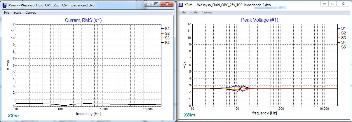
This is with 10 watt applied to see the graph more clearly.
S1 to S5 are in series and form one of the 5 strings of drivers connected in parallel.
If I do the same plots of Owen's parallel drivers:
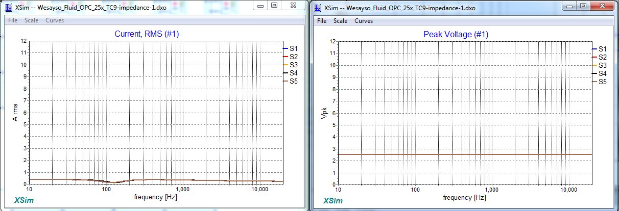
Here S1 to S5 are parallel and form one of the strings of drivers in series.
Again 10 watt applied to the complete array.
I think Owen (OPC) might be the brightest one here
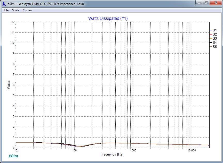
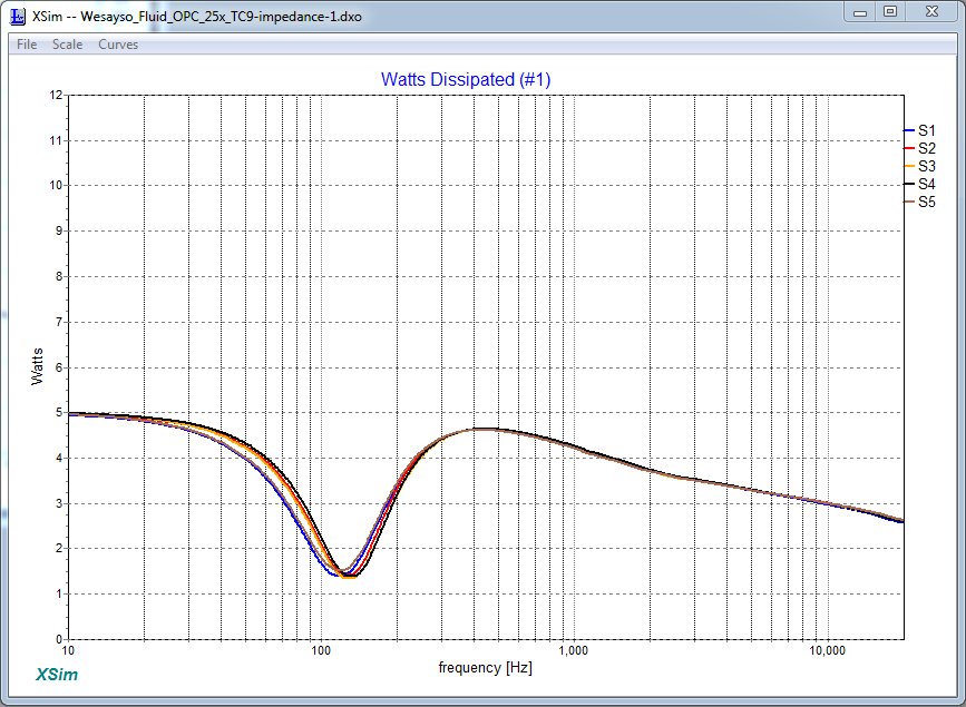
Let's look at the watts for both of these cases:
First in series:
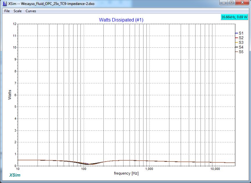
versus in parallel:
This is only a first look but I genuinely think Owen was on to something here.
Lets pump up the watts, plot it at 100 watt into the array!
First the series connected drivers:
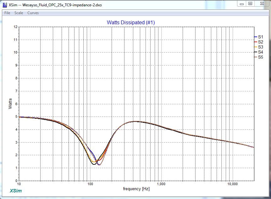
Then the parallel connected drivers:
Thanks to BYRTT for supplying the sims, to OPC for opening my eyes, to bwaslo for the amazing X-Sim program and fluid for the hospitality on this thread
These sims are just based on the separate impedance plots and joining them together. They don't show what happens if they share a common volume.
OPC shared a very similar story to Dr. Geddes here.
http://www.diyaudio.com/forums/full-range/303417-range-tc9-line-array-cnc-cabinet-38.html#post5087892
The sims do show quite a bit of difference. They are made from separate impedance plots of a real 25 driver set.
Last edited:
However due to the multiple sources a lot of other small things in the room get "averaged" out. Because the separate drivers all have their reflections at a slightly different timing... I do see their drop of only 3 dB for each doubling of distance as another advantage.
In a reflection all drivers are 'visible' to the ear. The "averaged" out behaviour of the line array is there in the direct sound as well as the reflected sound. A wall or floor or ceiling, all would make the entire array "visible" to the ear at least at lower frequencies. So, there is no benefit as far as reflections are concerned.
The 3db for each doubling may have a detrimental affect, not sure whether it is a problem sonically.
Consider a point source which produces 70dB at listening position at 2 meters and reflected wave travels 4 metres (double, for simplicity) so its at 64 dB.
ow, consider a line array that produces same 70dB. The reflection is stronger at 67dB. It may be an issue.
- Home
- Loudspeakers
- Multi-Way
- Line Arrays, directivity and impulse response