Interesting topic right here as I am currently building a large 3-way main system replicating ATC SCM100 and lately I was investigating how to line the cabinet inside.
I first thought of 8cm egg-crate but then came to the conclusion I better line the cabinet with bitumen and fill its internal with some kind of wool or polyester.
I think egg-crate might be effective for high frequencies and flutter-echos but that's it
Foam can be very effective from 250Hz up.
6" have an absorption coefficient of 1.12 at that frequency and 4" still have 0.9.
Pretty much ideal for ported boxes IMO and totally predictable. Unlike loose stuffing with wool/polyester.
")
http://commercial-acoustics.com/wp-content/uploads/2016/04/CA-Acoustical-Foam.pdf
Does this mean you have a sealed 2 way with no stuffing?
It means that I'm at the point right now where it's relevant to start experimenting with stuffing/lining. I'm not finished with the build. So there's nothing to listen to, at the moment. But the original plans were for a cuboid enclosure, where mine are a much smoother prismatic shape. So, the nature of my question was entirely in regards to my strategy for fine tuning the last little bits.
In a subwoofer cabinet there is no high frequency sound to absorb and lowering the Q is often not required and so stuffing may serve no beneficial purpose.
If the cabinet is stiff with the lowest resonances well above the passband of the driver then breaking symmetry won't matter because the modes won't be driven. In fact, symmetry can be beneficial if the driver is placed so that symmetric modes are not driven.
I really tried to run my braces through the centerline of the fastener holes, with the idea of canceling mechanical forces.
I know that it's a separate issue, but the subwoofer will be coupled to my floor by a spikes setting on granite. The granite will have tack (as in sticky goop) applied to the bottom, to keep them anchored in the spot that I finalize.
In a nutshell, every strategy you employ to solve an acoustic problem, whether it's standing waves, rear wall reflections, cabinet wall sound transmission and/or cabinet wall resonances/vibrations (whether acoustical or mechanical) are frequency dependent.
So as has been mentioned, loose wool or polyfill work well absorbing high frequencies but are useless in a subwoofer. As Mr. Darwin suggests, foam may work well down into the low hundred Hz but you need something with even more density and thickness to start aborbing frequencies lower than that. Increasing wall mass and damping might be called for to lower the walls' natural resonances below the passband of a mid in a 3-way but you want to use lot's of bracing and stiffness to raise the walls' resonances above the passband of the woofer or sub.
Here's an excellent chart on different material absorption coefficients that might help you: http://www.bobgolds.com/AbsorptionCoefficients.htm
In your case with a 2-way, you have to deal with almost the whole frequency range at once and so every strategy you employ is going to be something of a compromise (1 of the reasons why 3-ways can be better than 2-ways). And you may be confused because different people go about it in different ways. Which might be another way of saying there may be more than 1 way that works well.
For a sealed 2-way, I personally like to oversize the box and then use a combination of different types of absorption materials. Thick, high density insulation like Roxul RockBoard at the back, sides, top and bottom, medium density foam inside that and perhaps a bit of polyfill behind the driver while still giving it enough room to breathe. For the cabinet, constrained layer damping if you can but otherwise, well braced and damped with thick and stiff walls at the same time.
Maybe it's too late now, but if you are doing a translam, you should look closely at what Magico did with their 1st Mini. Curved thick walls well damped and braced and threaded rods to further increase cabinet and front and back baffle stiffness. Aluminum front and back if you want to go that far too.
Maybe it's too late now, but if you are doing a translam, you should look closely at what Magico did with their 1st Mini. Curved thick walls well damped and braced and threaded rods to further increase cabinet and front and back baffle stiffness. Aluminum front and back if you want to go that far too.
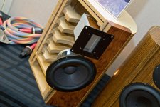
I actually did most of that. The walls are really thick - 1-7/16", to be precise. The bracing corresponds to the woofer, to break up the standing wave, and also to help disperse mechanical vibration. The threaded rods will take the place of my alignment holes when it's all said and done. (they provide the additional benefit of preventing delamination - which has really never been a problem in 10 years on my first translam build) And yes, I did a 1/2" thick aluminum baffle. But I only have a baffle on the front. I just increased the thickness on the back face, instead of adding more metal.
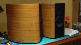
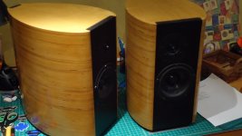
These are sealed, and intended to be used primarily with a subwoofer, but could also be standalone. I'm right in the middle of the recommended volume. Madisound gives a recommendation of .6 to .8 cu ft. on the enclosures, and I'm just a pinch over .7. So, I have some room to play.
I think we are thinking differently re the threaded rods. It sounds like you are using yours vertically inside the walls of the translam to help secure all the layers together. Which is great - no problem there. Maybe fill any empty space around the rods with sand. Or even look at what Selah Audio did with their Cirrus below, cutting out a cavity in the walls and filling it with sand.
Magico uses their rods horizontally, front to back to secure the front and rear baffles to the cabinet. Given the curve of the cabinet walls and the simple 'X' shape of the bracing, some flexing is inherent in the design so that stiffness is further increased when the front and back are pulled tightly together. The mechanical attachment of front and rear aluminum baffles with the rods may have some benefit in terms of keeping driver mechanical vibrations within that system but I'm nowhere near knowledgeable to say if that's true or not.
Magico uses their rods horizontally, front to back to secure the front and rear baffles to the cabinet. Given the curve of the cabinet walls and the simple 'X' shape of the bracing, some flexing is inherent in the design so that stiffness is further increased when the front and back are pulled tightly together. The mechanical attachment of front and rear aluminum baffles with the rods may have some benefit in terms of keeping driver mechanical vibrations within that system but I'm nowhere near knowledgeable to say if that's true or not.
Attachments
Yeah, I know what you mean, there.
To be perfectly honest, the Magico Mini is completely overdesigned. The torquing of the front and rear baffle to preload the X-stiffener is a nice thought, but were an actual finite element analysis to be performed on this, you'd find that the actual benefit is well past the point of diminishing returns. There simply isn't enough energy in that driver to overcome that enclosure to any significant degree. But engineers will engineer. (I'm a mechanical engineer LOL)
I designed my bracing such that the centerline of the bracing runs through my vertical alignment holes. More of a consideration during fabrication, than actual use. I'm 100% convinced that even with zero x-bracing, this enclosure would still function beautifully. But when I started learning about standing waves, I figured what the hell... Throw a couple in there. And, as previously stated, it should also stiffen the baffle, by resolving any moments from the movement of the driver, into some other area of the enclosure. Then, the horizontal centerline of the brace resolves into to the vertical centerline of the torqued threaded rods. Again, over-engineered, but a nice little project, nonetheless.
The sand pocket is interesting, but sounds like a real PITA to do right. For that to really work, wouldn't you have to completely isolate the inner and outer walls with a layer of sand insulation? As in, not a single piece of wood acting as a transmission line through the sand?
I found a way of testing stuffing/dispersion ideas.
You need a function generator, amplifier, scope and microphone (doesn't need to be high quality)
Connect the function generator to amplifier through a small capacitor (I think I used 10nF)
Set to a low frequency square wave like 0.1Hz and turn the volume up till you can hear clicks from the speaker
Connect mic to scope input and function generator to scope trigger
Point mic at speaker cone
You should see the clicks reflecting off different things inside the box on the scope
(I might have bypassed the crossover for this and just used the woofer - it was a long time ago)
The biggest one for mine was the woofer magnet
Hope that helps,
Brian
I actually did most of that. The walls are really thick - 1-7/16", to be precise. The bracing corresponds to the woofer, to break up the standing wave, and also to help disperse mechanical vibration. The threaded rods will take the place of my alignment holes when it's all said and done. (they provide the additional benefit of preventing delamination - which has really never been a problem in 10 years on my first translam build) And yes, I did a 1/2" thick aluminum baffle. But I only have a baffle on the front. I just increased the thickness on the back face, instead of adding more metal.
These are sealed, and intended to be used primarily with a subwoofer, but could also be standalone. I'm right in the middle of the recommended volume. Madisound gives a recommendation of .6 to .8 cu ft. on the enclosures, and I'm just a pinch over .7. So, I have some room to play.
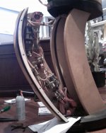
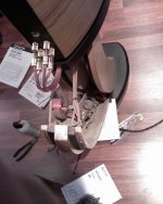
It sounds like you are doing something very similar to what I did (see attached). Walls about 1 1/2" thick, 4 or 5 Magico style X braces (5 or 6? - I can't remember now 10 yrs later), front and rear 1/2" aluminum baffles with horizontal threaded rods but no vertical rods. Xo's are in the stands.
The baffles and cabinet interior got several coats of sound dampening paint (something like QuietCoat) although in retrospect, it's probably only important for the aluminum. The baffles were then painted while the cab interiors got another layer of 1/8" bitumyn pads (or maybe 2, again memory fails me) before stuffing the back, top and bottom with RockBoard and the rest with polyfill, still leaving room behind the driver for it to breath. I stuffed the Roxul into wool socks to ensure no stray fibers would ever get near the drivers.
The results absolutely blew me away, mind you those are rather good drivers to start with. If I did it again today, I would probably make the cabs a little bit deeper and wider to accommodate a little bit more of the RockBoard insulation around the interior perimeter but I wouldn't worry at all about some kind of interior convoluted wall surfaces.
Hope that helps.
Attachments
That is way over my head... You electronics guys speak a funny language.
Clicks sent to the speaker travel direct from the front of the cone to the microphone and also from the back of the cone inside the cabinet. These are reflected off anything in the box and come back through the speaker cone. A microphone can pick these up and a scope can display them. Hope that's a bit clearer - I'm not great with descriptions

Gotta be any number of oscilloscope apps for Windows or Apple OS machines, maybe even tablets?
Yeah, I was wondering about something along those lines... But I'd imagine that the weak link would be the microphone, no?
Smartphone microphones are generally excellent, so I wouldn’t worry about that. Just tried SignalScope X on iPhone and it looks like it would do the job from a measurement point of view. Just got to find a way of generating clicks. I am traveling for a while, so can’t test unfortunately
- Status
- This old topic is closed. If you want to reopen this topic, contact a moderator using the "Report Post" button.
- Home
- Loudspeakers
- Multi-Way
- Innerchoic cabinets - should I?