Completed my IPL Transmission Line project and have written a huge 12 page review. Lots of stuff on forums elsewhere, which I've tried not to replicate, instead I'm trying to pass on the knowledge that I've gained as a beginner to DIY speaker building.
I hope this helps everyone, and if you're in the UK I really recommend these IPL kits.
Thanks
I hope this helps everyone, and if you're in the UK I really recommend these IPL kits.
Thanks
Attachments
Thanx for that… i haven’t read the whole thing, but this bit seems like non-sense:
dave
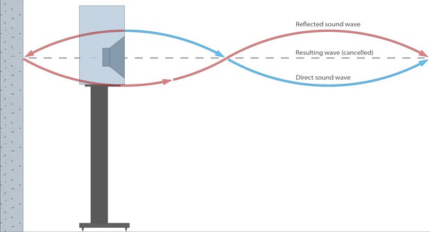
The transmission line speaker design helps by effectively stopping the
sound wave from the back of the speaker driver reflecting off the wall behind the speaker (the front wall) and then bouncing back towards the front of the speaker causing an acoustic null – this reflection is a major factor in good sound production.
dave
Hi Dave - yes I struggled in writing this part. Basically what I'm trying to say is that the sound from the rear of the speaker driver is effectively eliminated in a transmission line design, with only frequencies 200Hz and lower leaving the front termination of the transmission line. This means that the bulk of frequencies 200Hz and higher are not emitted towards the wall behind the speaker (the front wall that the listener is facing) - and therefore cannot go on to produce acoustic nulls. I hope this makes sense?
For someone like me who is trying to achieve good sound quality, but in near wall placement, it made a big difference.
For someone like me who is trying to achieve good sound quality, but in near wall placement, it made a big difference.
Hi Dave - yes I struggled in writing this part. Basically what I'm trying to say is that the sound from the rear of the speaker driver is effectively eliminated in a transmission line design, with only frequencies 200Hz and lower leaving the front termination of the transmission line. This means that the bulk of frequencies 200Hz and higher are not emitted towards the wall behind the speaker (the front wall that the listener is facing) - and therefore cannot go on to produce acoustic nulls. I hope this makes sense?
http://arqen.com/wp-content/gallery...nt/speaker-boundary-interference-response.jpg
For someone like me who is trying to achieve good sound quality, but in near wall placement, it made a big difference.
That it is a TL has some advantages. Those 180 bends the sound waves transit act as filters to reduce/remove higher frequencies. The lining and stuffing of the TL also tend to do this. Some reduction in reflections through the driver and some reducing higher frequencies passing through the line to exit the port.
The front foot placement of the port helps. It is physically remote from the woofer and close to a dispersing surface, the floor. Could also be an absorbing surface if carpetted.
What you are left with in terms of a problem(?!?) or not.... Is the group delay inherent in the sound reinforcment through the port. Which will be at its maximum at the TL tuned frequency. If that frequency is low enough, however, all manner of other room and furniture effects might make more of an impact.
J.
Hi Dave - yes I struggled in writing this part. Basically what I'm trying to say is that the sound from the rear of the speaker driver is effectively eliminated in a transmission line design, with only frequencies 200Hz and lower leaving the front termination of the transmission line. This means that the bulk of frequencies 200Hz and higher are not emitted towards the wall behind the speaker (the front wall that the listener is facing) - and therefore cannot go on to produce acoustic nulls. I hope this makes sense?
http://arqen.com/wp-content/gallery/room-setup-speaker-placement/speaker-boundary-interference-response.jpg
For someone like me who is trying to achieve good sound quality, but in near wall placement, it made a big difference.
Er -that's still nonsense I'm afraid. Unless your speaker is built into the room & is entirely flush with the front wall, it is a nominal monopole attempting to radiate into 2pi space below the baffle-step frequency. It doesn't matter whether it is a TL / QW, vented box variation, horn, sealed or anything else. Above the baffle step frequency, where the drivers are nominally emitting in 4pi space, it makes no difference what the enclosure internal load is and the radiation angle is governed by the driver characteristics & the baffle size & shape. Identical drivers on an identically sized & shaped baffle will behave the same way.
Hi ScottMoose - definitely agree that “Unless your speaker is built into the room & is entirely flush with the front wall” statement, but the transmission line design does tend to help with this aspect, probably more so in the lower frequencies. This is my subjective opinion
My experience is distance from the front wall either has to be small as possible, soffit mounting being the ultimate in this regard, or as far away as possible so that reflections are delayed, attenuated and diffused, and appropriate baffle step compensation. A transmission line is still a monopole source, a cardioid speaker can help with close front wall positioning
Last edited:
Any DIY versions of 3 way cardioid speaker, like these maybe :
Krypton3 | Amphion
Are the Dutch & Dutch 8C and Kii Three’s Cardioid?
Krypton3 | Amphion
Are the Dutch & Dutch 8C and Kii Three’s Cardioid?
Good to see an interest in DIY speakers and, in particular, room responses. The construction information looks good and useful but, as others have pointed out above, you are a bit wonky in places on the technical side.Lots of stuff on forums elsewhere, which I've tried not to replicate, instead I'm trying to pass on the knowledge that I've gained as a beginner to DIY speaker building.
In terms of room integration your 6.5" 2 way speaker is no different to any other 6.5" 2 way speaker except around the tuning frequency (which is what?) most of the sound is emitted near the floor. This will make a difference but whether for the better or worse is unclear. The frequency is likely too low to help with floor bounce (direct sound and sound bouncing off the floor cancelling).
As mentioned above, the design of your speaker does nothing to eliminate the cancellation off the front wall. If you place the speakers close to the front wall the baffle step correction in the crossover will likely need reducing although this can be successfully tackled with your room correction software. An example of a DIY transmission line type speaker that is designed to be placed flat against the wall is the Daline from the 70s. Note it is wide and shallow to reduce the effect of the reflection off the front wall. An alternative approach is to place the woofer/s on the side next to the front wall and the midrange on the front far enough forward for the first front wall cancellation frequency from the midrange to be below woofer/midrange crossover frequency. The progressive beaming of the midrange with frequency then reduces the strength of the higher order cancellation frequencies.
That is accurate, or it can be (although a competently designed box of other varieties should do similar). To apply it to external conditions though is nonsense, unless we're going to chuck basic laws of physics into the bin.
What you may be hearing is simply a better damped bass alignment which interacts with the room differently. TLs of the IPL type tend to do this well, as they typically target a well-damped LF response. That's the primary reason they can work quite well near boundaries. Another possible cause is simply hearing the difference between a speaker of different size with different drivers mounted in different positions from previous speakers in the same space. Both of these are well-known factors & I doubt anyone would disagree that they can & do have a significant impact on behavior. But assuming the same drivers mounted on baffles of identical size & shape, with identical vent positions, the dispersion pattern of a 40Hz wavelength (for e.g.) couldn't give two hoots whether it was generated by standing waves or cavity resonance.
Which shouldn't take away from the congratulations on your build. IPL make nice kits.")
What you may be hearing is simply a better damped bass alignment which interacts with the room differently. TLs of the IPL type tend to do this well, as they typically target a well-damped LF response. That's the primary reason they can work quite well near boundaries. Another possible cause is simply hearing the difference between a speaker of different size with different drivers mounted in different positions from previous speakers in the same space. Both of these are well-known factors & I doubt anyone would disagree that they can & do have a significant impact on behavior. But assuming the same drivers mounted on baffles of identical size & shape, with identical vent positions, the dispersion pattern of a 40Hz wavelength (for e.g.) couldn't give two hoots whether it was generated by standing waves or cavity resonance.
Which shouldn't take away from the congratulations on your build. IPL make nice kits.
Last edited:
I have a couple of B110s and T27s with nothing to doAn example of a DIY transmission line type speaker that is designed to be placed flat against the wall is the Daline from the 70s. Note it is wide and shallow to reduce the effect of the reflection off the front wall.
I can personally attest this http://www.ejjordan.co.uk/PDFs/Eikona_VTL.pdf works well against the front wall
...Basically what I'm trying to say is that the sound from the rear of the speaker driver is effectively eliminated in a transmission line design, with only frequencies 200Hz and lower leaving the front termination of the transmission line. This means that the bulk of frequencies 200Hz and higher are not emitted towards the wall behind the speaker (the front wall that the listener is facing) - and therefore cannot go on to produce acoustic nulls. I hope this makes sense?
I phrase that idea as “the TL sucks the backwave down the line and damps it out”.
Sometimes a line will use some of that output to reinforce the bass (likely in your IPL from the limited amount of damping). One tries to keep the main line harmonic and kill all the harmonics above it as they will cause ripple as they move in and out of phase with the output from the front of the speaker. The desired bandwidth is much smaller than “under 200 Hz”.
The issue that your diagram is showing is independent of the box type and is related to the radiation from the front of the speaker. It is caused by the distance of the speaker from the wall.
Your IPL is end-loaded and the only measure to mitigate ripple is the pre-chamber. Earlier in the week i speculated about a similar “daline” that mounting the driver on the “back” would get one some driver offset and help kill ripple.
IPL has been shipping TL kits since before good TL modelers arrived on the scene and still use the same classic design scheme. Not to say that the results ar enot satisfying, but one wonders if their performance couls be further improved with a little tweaking.
For someone like me who is trying to achieve good sound quality, but in near wall placement, it made a big difference.
As stated earlier, the TL aspect of your speaker has no affect on the issue of ripple caused by the distance to the front wall (i personaly think of it as the back wall, as in the wall behind the speaker). That distance only has an affect on the frequensies at which the ripple occurs.
dave
Attachments
...or as far away as possible so that reflections are delayed...
Distance affects the frequencies at which things start to happen. Move far enuff away and they start to get buried in the room response.
dave
If you place the speakers close to the front wall the baffle step correction in the crossover will likely need reducing although this can be successfully tackled with your room correction software. An example of a DIY transmission line type speaker that is designed to be placed flat against the wall...
Scott and i have recently revisted this idea. It uses an ML-TL with bass tuning that is intended to work well with near or on wall placement. Wide and shallow tends to minimize the room placement issue that stretchneck has been erroneously associated with a TL.
http://wodendesign.com/planset/Poplar-A10x-MLTL-teaser.pdf
dave
With respect to wall placement it is similar in concept to the Daline and I would expect this to work fairly well. However, the drawing specifies no damping in the line which has turns and step changes in area. If damping is not specified elsewhere this will let all the line modes through not just the lowest plus it will have resonances associated with the height of the speaker. The stuffing at the top is likely sufficient to damp higher frequencies but the lowest few unwanted modes I would expect to be significant and audible. Measurements would show one way or the other.I can personally attest this http://www.ejjordan.co.uk/PDFs/Eikona_VTL.pdf works well against the front wall
... it is similar in concept to the Daline and I would expect this to work fairly well...
Sims show that the Jordan VTL does not work well… Scott has removed the back from his pair and turned them into an OB.
dave
- Status
- This old topic is closed. If you want to reopen this topic, contact a moderator using the "Report Post" button.
- Home
- Loudspeakers
- Multi-Way
- Achieving full range sound in typical British living rooms - IPL Speakers S2TLK CD3.0