With my pocket RTA I see a 15db peak above ambient around 16khz with the mic about 1cm from the silk dome. Obviously this is ridiculously close, but I can definitely hear it in a silent room if they are setup as near field monitors. The right speaker is actually a bit noisier. Correct me if i'm wrong, but 16k should be a harmonic of the 400khz switching frequency.
Last edited:
All regulator outputcaps have small smd ceramic bypasses I believe, that could be the source of noise peak ??
Using 3-pin regulators off-piste: part 3
Using 3-pin regulators off-piste: part 3
I listen to my 305's near field, and they are really quiet, I don't hear any hiss or noise like he describes.
I have heard other reports of hiss though.
Do you guys have that problem?
Put your ear up to the speaker. I can hear it from a few feet away in a quiet room.
Does it change at all with the input unplugged?
I don't think so but I will double check on the weekend.
I checked my again, and I could hear some hiss if nothing was on. My left speaker was worse. Right one had to be within one foot, and maybe three feet on the left one. But this was with ear turned toward speaker, and at those distances, it was barely audible.
So even at my nearfield distances I don't hear it at all.
So even at my nearfield distances I don't hear it at all.
Hello together
For those who want to look a little deeper into Electronics I have extracted Schematic from Analog section.
- Coupling Capacitors to Opamp are Electrolytic Type 100uf. I do not believe
that Film Caps sound better. Nevertheless I changed them because of
reliability. I had already several Electrolythical caps in the past which get
"dry" with the time. Attached Picture shows Wima Foil caps with 6,8uF.
Space is very limited, bending of Lead wires is necessary.
- OPamp Mod. Used OPamp is NJM2115. I did not change because I do not
believe in Sound difference of OPamps.
Mods that have effect on Sound:
- Buffer capacitor change of STA350BW changed form 1000uF/35V to
4700uf/35V (Dark Blue Capacitor, please refer to attached picture)
- Capacitor on Filt+ Pin of CS5341 AD Converter:
According to latest Datasheet of CS5341 100uF decreases Distortion Level
at low Frequencies dramatical compared to used 1uf in current PCBA
(Light blue capacitor, please refer to attached picture)
How does it sound compared to unmodified Electronic:
More Punch and cleaner sound. Test it
Have fun
Eljo
Well I just ordered the caps to try this little mod. Went ahead and ordered some film coupling caps in 4.7uf since I figured a balanced input will play better with closely matched coupling caps for summing the signal. According to the coupling cap calculation, a 4.7uf seems optimal for frequencies above 20hz with a 22k input impedance.
I ordered standard electrolytics for the ADC and amp buffer capacitors. I'm curious if a low ESR would be of any advantage for either of these caps.
Will get back when I've installed them.
Doing a bit more research, I found some possible room for improvement. The datasheet for the STA350BW demo board has lots of good info about propper layout design and component selection. On page 18 it gives recommended values for the output filter which is a BTL hybrid filter. The LSR305 uses 15uH inductors for both the 8 ohm tweeter and 4 ohm woofer, but according to the datasheet, it should ideally be 22uH for 8 ohm and 10uh for 4 ohm. You would need to change the respective capacitors as well. The output filter design could also be improved by converting the hybrid filter, chosen for its low cost, to a common mode filter as described in this fine write-up on class-d filters.
Hope this can be of use to someone, let me know what you think.
Hope this can be of use to someone, let me know what you think.
I bought a pair of these (following Salas' advice) to be used as monitors in my workshop. I was amazed at how much value 2 x 99€ got me. They have no problem filling up my 40 sq.m living room, so they will kill it at my workshop.
I'll keep an eye on this thread for possible DIY improvement..
I'll keep an eye on this thread for possible DIY improvement..
Congratulations! Check what Elac did for the Debut 2.0! Debut 2.0 – Elac
The crossbrace!
An externally hosted image should be here but it was not working when we last tested it.
The crossbrace!
Last edited:
")
Juhazi, thanks for the write-up and measurements of your mod! I've been using these speakers for about 3 years and have been quite impressed, but i'm always looking for diy mods. I'll be trying this one soon.
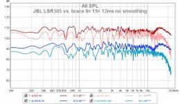
Did you happen to get measurements for your cross braced cabs with the back plates installed? It would be nice to see an overlayed response graph of both the modded cab and the stock cab fully assembled. My apologies if you already did this.
Did you happen to get measurements for your cross braced cabs with the back plates installed? It would be nice to see an overlayed response graph of both the modded cab and the stock cab fully assembled. My apologies if you already did this.
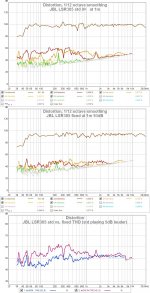
I checked my measurements again, here better comparison of std vs. with center brace fix. Spl for distortion measurement is not equal - look at distortion details more than percentage!
In 0/30¤ response measurements diffrerences come mostly from slightly different position of speaker and microphone.
I can't help with dsp tweaking, sorry!
In 0/30¤ response measurements diffrerences come mostly from slightly different position of speaker and microphone.
I can't help with dsp tweaking, sorry!
Attachments
Last edited:
Mods that have effect on Sound:
- Buffer capacitor change of STA350BW changed form 1000uF/35V to
4700uf/35V (Dark Blue Capacitor, please refer to attached picture)
- Capacitor on Filt+ Pin of CS5341 AD Converter:
According to latest Datasheet of CS5341 100uF decreases Distortion Level
at low Frequencies dramatical compared to used 1uf in current PCBA
(Light blue capacitor, please refer to attached picture)
How does it sound compared to unmodified Electronic:
More Punch and cleaner sound. Test it
Eljo
Is the big 4700uf one low ESR or just a regular cap?
Did any of these changes reduce the hiss?
It theory you should upgrade all big caps, staring with the ones in the power supply.
STA350BW datasheet says it can achieve SNR around 90-100dB, some standalone amps based on this chip claim to have an SNR of 90dB, but the specs of the new Jbl 30Xp mk2 series only list 75dB, And since it probably only achieves this figure near the 100+db SPL, at lower volumes it sounds like a (very good) cassette deck with some Dolby NR. Would be fine in 1990, but non in 2019.
Re the hiss - in my case if I turn the volume all the way down before powering up - when I power it up - it is dead silent. Then when I rotate the volume knob one click at a time - at 0.5 the hiss is there but very quiet (but also no signal). Checked with an oscilloscope and I can see the 384kHz carrier and its harmonics in FFT mode, very sharp spikes, no noise. As soon as I increase the volume even by a single click the spectrum becomes quite noisy and the hiss becomes much louder. At this point turning down the volume to 0 and back to 0.5 does not help - you immediately get that loud hiss and noisy spectrum. The only way to get that clean spectrum is to turn the speaker off completely and start from volume 0.
I tried replacing most electrolytics on power rails to low ESR Panasonic caps - exactly zero effect. Put some 0402 0.1uf SMD caps directly on both 3.3V VDD_DIG pins - also no effect.
So my only theory at this point is that this behavior (noisy 384kHz carrier spectrum & loud hiss) is caused by high frequency noise on the 3.3V rail of the STA350BW chip originating from its digital circuitry and leaking into the PLL filter's power supply.
So probably when the chip is first powered up, its digital section doesn't do much and does not generate much noise on its power pins. But when the volume is turned up, all that digital circuitry is actively processing the input signal and interfering with the PLL.
ST docs say this:
The reason that the VDD_DIG and PLL_VDD pins are separated with beads is to avoid high
frequencies on VDD_DIG. It is possible to eliminate these components if the layout is done
with a right star connection.
So I ordered some 0603 SMD ferrite beads and plan to try replacing 0 and 2.2 Ohm resistors R212 and R213 (R31 and R32 in STA350 datasheet) with ferrite beads.
Might help.
- Home
- Loudspeakers
- Multi-Way
- JBL LSR305 tweaking