Way better
I now added a headphone jack to my measurement jig to measure with the headphone out of my behringer.

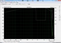
The measurement of the 3R9 resistor looks a lot better compared to the one with the line level outputs, but still has the issue.

Im now going to try to measure the impedance with the speaker hooked up to the amplifier.
I now added a headphone jack to my measurement jig to measure with the headphone out of my behringer.
The measurement of the 3R9 resistor looks a lot better compared to the one with the line level outputs, but still has the issue.
Im now going to try to measure the impedance with the speaker hooked up to the amplifier.
Last edited:
Im now going to try to measure the impedance with the speaker hooked up to the amplifier.
You won't get good data below 100 Hz.
Did you set the volume of the phones out to max.?
Do you have another soundcard to try? Maybe your computer has a built audio in/out?
finally got a good measurement
Today i tried to measure the 3R9 resistor with the headphone out and mic in of my laptop and the measurement looks fantastic.

So my final advice is not to use the behringer UCA 222 for impedance measurement, the headphone output on your computer is probably better for impedance measurements.
Thank you all for your helpful suggestions, now i can finally measure correct impedance curves.
Today i tried to measure the 3R9 resistor with the headphone out and mic in of my laptop and the measurement looks fantastic.
So my final advice is not to use the behringer UCA 222 for impedance measurement, the headphone output on your computer is probably better for impedance measurements.
Thank you all for your helpful suggestions, now i can finally measure correct impedance curves.
Last edited:
Mario, can this small Behringer sound card measure a resistor impedance to be a flat line or not, from start to beginning? Inductive audio resistors are not a problem, they measure ruler flat to 20 kHz.
Ralf already posted results before me, sorry was away. I may run one with mine, its modified and can deliver higher current, in short - yes it can be used but not in its stock form.
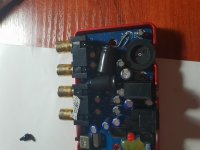
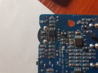
The rise in impedance below impedance peak is caused by this Behringer`s layout. It is DC coupled and has 100uF output capacitors on the headphone out (and the output RCAs). And they cause the rising impedance below Fs. Mod is easy - change the opamp to a better one (it has a 4560 inside which is glued to the PCB) like an AD8565, remove completely the output 47R resistors (short them) and replace the outptu caps with largest possible - I managed to fit 1800uF 6.3V Panasonic FR inside and when set at full power, the rise is gone even with 4 ohm drivers.
I took mine apart. The resistors that are in series with the headphone amp output are R36 and R41 - both around 47R. You can short them. The caps are C15 and C16 to the opposite part of the PCB. Here you put the largest possible that can fit, these are 1800uF 6.3V Panasonic FR - pretty compact. You can also replace the headphone chip to an AD8656 without any modifications, will work fine (its made for low voltage rail) and sound better than the original one. Around EUR 3 from farnell.
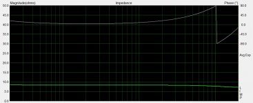
And finally, an impedance measurement on a 8 ohm resistor after the mod. Note the decline in the region above 10Khz, at 20Khz the cursor showed 7.15 ohms on a 8 ohm resistor. Not sure of the cause - there are two inductors on the PCB which might be on the output but I didn`t go that far.
Despite its pretty good performance, it would be much better to use a USB interface that has no output capacitors or so, like the M Audio or Focusrite series.
Attachments
For most drivers, impedance is a microscope for determining cone motion and a key piece of information.
Anything marked as a headphone output isn't a reliable source since there can be series resistors and EQ.
Maybe my old lab instincts are too untrusting, but I try to make the fewest assumptions about the hardware or the software. I simply bracket the impedance range of interest with two resistors and overlay the resistor plots and the speaker. For sure, you want to know the relative impedance freq envelope with some accuracy, but rare to need a precise knowledge of the impedance. If it is screwing up your crossover, you need to rethink your topology.
Takes less time too. See post 2 (fourth chart) for an illustration of bracketing with 7- and 47-Ohm resistors:
17 foot pipe sub 12-230 Hz ±5dB
B.
Last edited:
Anything marked as a headphone output isn't a reliable source since there can be series resistors and EQ.
That depends on the measurement set up, and on how the software does the calculations. The ADC channels should be hooked up such that one channel (REF) is used to determine the current through the REF resistor, and the other channel (DUT) is used to determine the voltage across the DUT. Since the current through the REF resistor is identical to the current through the DUT, the software should then calculate the impedance as the DUT-voltage / REF-current. Even if the current out of a mediocre sound card is limited, the software should be able to work out the correct current from the two-channel measurement (REF+DUT channels).
Do you know what your software does?
Your elaborate description seems, well, elaborate. I'd rather be quick and dirty if it gets the information I need in a trustworthy manner.That depends..
Do you know what your software does?
On a good day, I might know what my software claims to do just as I might think I know what a headphone amp claims to do. But I know that some the time I set my REW parameters funny and some of the time I don't know it.
Do you check the code line by line? It is possible to verify that the software seems to be working like it should and doing so is good practice. But that just adds one more layer of elaboration.
B.
Last edited:
Hi,
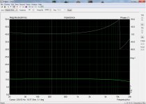
Recently I tried a measurement setup with ARTA - 100 0hm ref resistor - and behringer UCA202 and I came across the problem mentioned in this thread. The subtle improvement using the headphone output made me think that adding a buffer could help so I inserted Pete Millett's soundcard interface and seems to work up to a point... First pic is a 10.3 0hm resistor - measured with DMM. I can't think of a remedy for the high frequency roll off but it should be OK for basic measurements. Second pic is the resonance frequency of a 107nF/1mH LC circuit. Accurate despite the strange phase plot.
Recently I tried a measurement setup with ARTA - 100 0hm ref resistor - and behringer UCA202 and I came across the problem mentioned in this thread. The subtle improvement using the headphone output made me think that adding a buffer could help so I inserted Pete Millett's soundcard interface and seems to work up to a point... First pic is a 10.3 0hm resistor - measured with DMM. I can't think of a remedy for the high frequency roll off but it should be OK for basic measurements. Second pic is the resonance frequency of a 107nF/1mH LC circuit. Accurate despite the strange phase plot.
Attachments
Hi,
Recently I tried a measurement setup with ARTA - 100 0hm ref resistor - and behringer UCA202 and I came across the problem mentioned in this thread. The subtle improvement using the headphone output made me think that adding a buffer could help so I inserted Pete Millett's soundcard interface and seems to work up to a point... First pic is a 10.3 0hm resistor - measured with DMM. I can't think of a remedy for the high frequency roll off but it should be OK for basic measurements. Second pic is the resonance frequency of a 107nF/1mH LC circuit. Accurate despite the strange phase plot.
Did you calibrate before measurement? Phase plot gives me a feeling that calibration is missing.
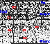
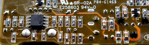
Anyone here got schematic of UCA222? I think the output is capacitor coupled. and the capacitor value is small .
I posted it in some of the previous pages. You have a 100uF cap on the output which might be ok for loads of 32 ohms or larger (headphones) but will have strong influence on a load of 4-8 ohms hence the issue with measurements and rising impedance. Replacing those with largest possible value (I managed to fit 1800uF Panasonic FR) solves the issue. I will post (in a few days) a direct comparison of the same driver, same conditions and a load resistor between the UCA222 (mine is modified with a AD8565 opamp and has no output resistors so can supply much higher current, compared to the original 4560 with 47R resistors) and an M Audio Fast Track Pro.
Note the decline in the region above 10Khz, at 20Khz the cursor showed 7.15 ohms on a 8 ohm resistor. Not sure of the cause - there are two inductors on the PCB which might be on the output but I didn`t go that far.
Try calibrate LIMP . Using calibration mode.
I posted it in some of the previous pages. You have a 100uF cap on the output which might be ok for loads of 32 ohms or larger (headphones) but will have strong influence on a load of 4-8 ohms hence the issue with measurements and rising impedance. Replacing those with largest possible value (I managed to fit 1800uF Panasonic FR) solves the issue. I will post (in a few days) a direct comparison of the same driver, same conditions and a load resistor between the UCA222 (mine is modified with a AD8565 opamp and has no output resistors so can supply much higher current, compared to the original 4560 with 47R resistors) and an M Audio Fast Track Pro.
Thanks Mario,
I could not back trace the whole circuit. But the 100uf cap seems to be like C2 in the attached image. which works like a HPF and like usually done. Its cutoff point seems to be 20Hz ( looking at the impedance offered).
Here the resistor is 470R instead of 47R. I seriously need Schematic for this.
Wondering if any of our group member has it.
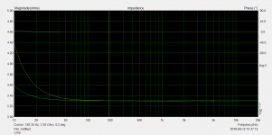
I am attaching a limp reading . I measured 3.3R resistor. and looks accurate . At 20 Hz error is of 0.07R and at 10Hz its 0.28R.
Attachments
Last edited:
- Status
- This old topic is closed. If you want to reopen this topic, contact a moderator using the "Report Post" button.
- Home
- Loudspeakers
- Multi-Way
- Problems with impedance measurement