Hi Gents,
I am going to be building a pair of somewhat unusual two ways soon. I have talked with tech support at Parts Express and they say that they think my idea will work but could not advise me as to some of the details of the build.
Specifically, I plan to use the PE 8" sub woofer part #295-484 crossing it at 500HZ to a Tymphany TC9FD18-08 PE part #264-1062. The planned crossover is the "textbook" hi pass of 5mH coil with 20uf cap and low pass of 2.5mH coil with 40uf cap.
This is not intended to be a great sounding speaker overall. It is more of an experiment to see if these super-affordable drivers can be paired to make a reasonably clean sounding speaker with very good bass.
I can come up with a pretty good ported cabinet design using WinISD Pro but as the thread title suggests don't have a clue as to the best size for the TC9FD "tweeter" chamber. PE tech support suggested .1 CF but that seems way to big for a driver being crossed over at 500HZ. In fact I'm wondering if a chamber is needed at all since the woofer is rolling off at 500HZ and the back of the tweeter cone may not be much affected by such low frequencies.
So, do I need a chamber and if so, what size?
Also is anyone aware of a "quick and dirty" crossover that would be a substantial improvement over the textbook one for these drivers in a project like this?
Again, I realize these are not going to sound great and know that "textbook" crossovers are not optimum, but I am eager to throw these together and see how they sound. All constructive input is very welcome and appreciated.
Best,
Jay
Last edited:
Many thanks for the input guys, it is very helpful. Two questions though. On the quick and dirty crossover in post 3, shouldn't the 24uf and 3.3mH leg of the tweeter circuit be attached to the + terminal of the tweet instead of the - shown in the diagram? Also, does this crossover take care of the BSC and tweeter attenuation described in post 2?
Thanks!
Thanks!
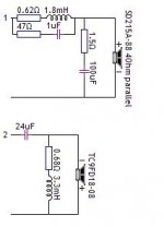
The 0.68 ohm and 0.62 ohm resistors are not actual resistors, but the DCR of the coils next to them. When it comes to 2 series components, the connection position does not matter. You could swap the 47 ohm and 1uF positions on that same series circuit, and nothing would change, as well as the 1.5 ohm and 100uF spots.
It looks like the BSC is accounted for, but the sensitivity may or may not be depending on how the drivers' sensitivities are matched after BSC.
He did say it was a quick and dirty simulation, so some adjustment will likely be required.
Later,
Wolf
It looks like the BSC is accounted for, but the sensitivity may or may not be depending on how the drivers' sensitivities are matched after BSC.
He did say it was a quick and dirty simulation, so some adjustment will likely be required.
Later,
Wolf
I've used the TC9-FD as a tweeter topping an 8" woofer many times. If it's in a box, it should get its own enclosure and I've found 1 liter, stuffed, to work just fine. I cross a little higher, circa 700 Hz and 1st order. The TC9-FD is fairly insensitive to back volume.
FWIW, I use 1st order because I tried combinations from 1st to 3rd and found that 1st order worked as well as any. That may be just a combination of drivers and crossover point. Have fun!
FWIW, I use 1st order because I tried combinations from 1st to 3rd and found that 1st order worked as well as any. That may be just a combination of drivers and crossover point. Have fun!
TC9 in 1 liter sealed and stuffed yields (WinISD sim) an impedance peak at ~180Hz, of fairly mild amplitude ~15 Ohm. I guess it should not interact too much with the response of a crossover at 500Hz or higher, even first order.
Otherwise, for drivers with a higher Qm and resulting impedance peak, I'd suggest a short, tapering and damped line, ~12" or so. This works well to flatten the impedance and use a nearby passive crossover.
Otherwise, for drivers with a higher Qm and resulting impedance peak, I'd suggest a short, tapering and damped line, ~12" or so. This works well to flatten the impedance and use a nearby passive crossover.
Since part of this project is about affordable and simple, I'm pretty excited about post 6 above suggesting that a first order crossover might work as well as a second order. If someone, perhaps Pano, could give details of what that crossover would look like I would greatly appreciate it. The only reason I chose 500HZ as the crossover point is because the Dayton 8" sub (PE #295-484) has a 5db trough from 1100 to 1400 HZ that I was trying to avoid.
I will start building the cabinets today, but will not be ordering crossover parts for this and another project I'm planing for until tomorrow, so my options are still open.
Also, I'm thinking, regarding my tweeter connection question in post 4, that the crossover kindly posted by Draki is correct as is and that the tweeter was meant to be connected in reverse polarity.
Thanks to All,
Jay
I did a number of sims of the TC9-FD with woofers and saw that 2nd or 3rd order would be best. But once I got them in the box, there just wasn't much difference. I'm not home now to look at what parts I use - I should remember, but I don't.  Coil on the 8", cap and resistor on the 3". Best for me not to guess, as I don't want to lead you astray.
You can pick up some cheap caps, coils, and resistors from P.E. and play around. That's what I did. Mostly the buyout stuff.
Certainly the crossover could be "better" but I really couldn't hear any improvement with more complex crossovers. I do remember putting a small coil in series with the TC9-FD to tame the top, but that depends on how on-axis you are. Off axis the the top end is OK.
Coil on the 8", cap and resistor on the 3". Best for me not to guess, as I don't want to lead you astray.You can pick up some cheap caps, coils, and resistors from P.E. and play around. That's what I did. Mostly the buyout stuff.
Certainly the crossover could be "better" but I really couldn't hear any improvement with more complex crossovers. I do remember putting a small coil in series with the TC9-FD to tame the top, but that depends on how on-axis you are. Off axis the the top end is OK.
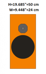
Your woofer is about 2.5dB higher in sensitivity, which is good to fill-in below baffle-step. You never need the full 6dB in a domestic environment IMO. If you can manage to size your baffle at about 9" wide, this will coincide with your 500Hz crossover and should require no more effort or parts as far as BSC goes. 9" might be a bit tight for your 8" woofer OTOH, so if you end-up making the enclosure a bit wider, just lower your crossover frequency to match.
343 / baffle-width / 3 = baffle-step frequency
Note that baffle-width is in meters here.
343 / baffle-width / 3 = baffle-step frequency
Note that baffle-width is in meters here.

Wow, this is getting pretty exciting for perhaps an even more economical build than anticipated. If I have done the math offered by IG81 correctly, for my 10 inch wide baffle I should cross over at 450HZ and, using the ERSE first order crossover calculator, put just a 44uf cap on the TC9FD and a 1.4 mH coil on the woofer.
Talk about a low cost easy to build speaker! However, if there would be a significant loss in sound quality, the crossover posted by Draki is pretty affordable and simple too. Any thoughts about which way to go? I promise to post my listening impressions when the build is done. I will compare them to a couple of more sophisticated DIY two way designs I've built.
Jay
Pano, Wolf and IG pretty much covered all topics.
The above xo simulation is just that - a simulation. It would be nice if you could measure the drivers in the actual enclosure, accurate measurements are basis for further meaningful xo design. There are many ways to skin a cat ...
The above xo simulation is just that - a simulation. It would be nice if you could measure the drivers in the actual enclosure, accurate measurements are basis for further meaningful xo design. There are many ways to skin a cat ...
It might not be a bad idea to use a Zobel on the woofer, especially if you want to go 1st order. The impedance is already rising fast by 500Hz, this can definitely mess things up.
As fun as envisioning a 1 coil + 1 cap 1st order crossover is, the implementation often requires a few more parts. I've seen some wildly complex 1st order designs floating around the net.
As fun as envisioning a 1 coil + 1 cap 1st order crossover is, the implementation often requires a few more parts. I've seen some wildly complex 1st order designs floating around the net.
Yes, for the 1st order: a Zobel for the woofer, plus LCR impedance trap and yet another Zobel for the TC9. Never mind the EQ...
At the end, bigger parts count for the nominal 1 coil + 1 cap "simple" xo.
Could be worth it at the end soundwise, but that is beyond this remark.
At the end, bigger parts count for the nominal 1 coil + 1 cap "simple" xo.
Could be worth it at the end soundwise, but that is beyond this remark.
Last edited:
You can get way with no Zobel if you pick the parts carefully. Sometimes the Zobel may be worth it, sometimes not. If you play around with some inexpensive parts, like non-polarized electrolytic caps and bargain inductors, you'll get a feel for what's going on.
But if you can measure in situ, as Draki says, you should be able to hit your target without much swapping a parts.
But if you can measure in situ, as Draki says, you should be able to hit your target without much swapping a parts.
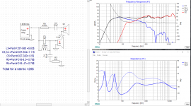
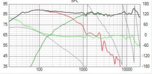
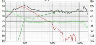
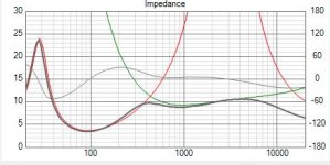
Lojzek, below is your exact xo (used - 200 mm for woofer Y, all zeroes for tc9) , wonder why is the spl diff in the bass so big? I am using PE zip files for FR and Z for the woofer, and traced FR and Z from Tymphany' pdf for the tc9.
Woofer is, I guess, measured with both coils in parallel. Like I said, why the spl diff? Impedance matches as far as I can see (above 100 Hz).
Woofer is, I guess, measured with both coils in parallel. Like I said, why the spl diff? Impedance matches as far as I can see (above 100 Hz).
Attachments
Last edited:
- Status
- This old topic is closed. If you want to reopen this topic, contact a moderator using the "Report Post" button.
- Home
- Loudspeakers
- Multi-Way
- Enclosure size for Tymphany TC9 FD-18-08 used as "tweeter"