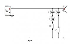
Why is C1 in series with C5? for a parallel network you'd normally run the tweeter circuit direct from source
My clumsy attempt at combining 2 networks

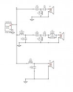
Nice, but I think it's useful to include phase of all drivers. On first inspection, the low cut of S2 looks better. But perhaps put L7 before C4? This might affect the values of C4 and C3, and I'm not sure if I'm correct here.
Also would be useful if you included the impedance response.
Also would be useful if you included the impedance response.
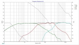
You can still see the response gain at the crossover.. +5dB for the lower and +6dB for the upper.Nice, but I think it's useful to include phase of all drivers.
G'day,
The ES180 is rated 84dB sensitive. the curves (assuming you sourced them from the daytonaudio website) show a nearfield splice below 450Hz. Therefore BSC has not been allowed for in your design. ie. you are showing a net 86 / 87dB design with a woofer only capable of 84dB below bafflestep frequencies. This means you'll be lacking in bass / have a brighter sound.
What is the impedance curve like?
Are you targeting LR acoustic slopes? If so, do you have a reverse null sim?
G'day,
...What is the impedance curve like?
Are you targeting LR acoustic slopes? If so, do you have a reverse null sim?
Hi Dave,
Appreciate your interest here.
I hope I have posted the info you asked for below. Let me repeat this is only my second attempt at a xo. I'm just trying to get a handle on the considerations that make up a good circuit... it's obvious even to me that it's more than a flat FR.
Thanks for the pointer re BSC/sensitivity error... just don't know how to correct it. Again I was attempting to design a base circuit around the 3 drivers I plan to use.
Many thanks
Dennis
Attachments
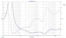
I'm an absolute beginner at crossovers myself, but your latest graph in post 27 looks like the tweeter and mid are out of phase? Try right clicking on the tweeter and clicking Invert/Normal. My 2cents for all its worth. I agree though, that impedance plot looks like an amp killer.
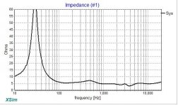
That impedance plot if correct is a potential amp killer.
Cheers rabbitz,
I got to wondering if the zma file I was using for the ES180TiA wasn't corrupt but I don't think so.
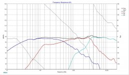
Below is the notch filter including zobel network that flattens the peak.
Attachments
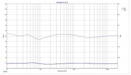
Yes. The major problem is phase - when the amplifier voltage and current are out of phase, the power in the output stage can be massive. In general, the amplifier must be capable of driving half the nominal impedance comfortably.
B&W have questionable nominal impedance ratings, like the 683 S2, which is claimed to be 8 ohms, yet drops to 3.2 ohms minimum, and I would rather have rated them 4 or 6 ohm. In my opinion, I would rate the posted impedance as 2.5 ohms nominal, so the amplifier would need to be comfortable with 1.25 ohms.
The biggest problem I see is at about 2.8 kHz where the impedance is <2 ohms and the phase is 45 degrees.
This is what I would consider a nice impedance curve...
http://www.diyaudio.com/forums/atta...n-2-tower-monitor-audio-bronze-5-a-fr_mtm-png
Last edited:
I've got a 3 way I'm designing and im managing to keep the impedance above 3.1 ohms. I'd say most 4 ohm nominal rated amps would be fine at 3 ohm minimum but your speaker has too many 1 to 2 ohm minimums
So the woofer's resonant peak is not the issue?
Mrcloc said:...The biggest problem I see is at about 2.8 kHz where the impedance is <2 ohms and the phase is 45 degrees...
This is the issue?
I have been reading this thread here, and a quote...
speaker dave said:The peak is an interaction between the high capacitive reactance above woofer resonance and the crossover. This is a real effect that give the most trouble when the woofer motional impedance (resonance bump) is tall and the crossover point is relativley close.
I'd second what AllenB said about itterating the values for your best result and also using high DCR inductors if you go for conjugate correction. Even with optimization you may still be fighting the effect.
Don't forget that you can try an acoustic resistance blanket over the back of the woofer to knock down the impedance peak. That would make life easier.
This isn't a resonance per se, but an interaction. If you find values or a different topology that gives flat response in the region, then you are done. No extra feedback or other fixes required.
David S
This is the issue?
For the amplifier. It's not an easy load.
There could be done something to improve the impedance profile, this one looking too much of a heavy load. I'd lose the large 40 uF, rework it to be smaller, get rid of the 3rd order HP for the midrange and organize the parts in a more traditional way, meaning first padding resistor then high pass filter and finally low pass. Yes, and add baffle step simulation as well. You can do that with Response Modeler easy. Midrange could probably be 8 ohm nominal and still loud enough.
Last edited:
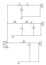
Ok, so let's look at that midrange crossover.
You have something like this:
Let's change it, but let's start with a LPF:
Let's add the baffle step correction:
Then we add in the HPF:
Nice impedance response too.
You have something like this:
An externally hosted image should be here but it was not working when we last tested it.
An externally hosted image should be here but it was not working when we last tested it.
Let's change it, but let's start with a LPF:
An externally hosted image should be here but it was not working when we last tested it.
An externally hosted image should be here but it was not working when we last tested it.
An externally hosted image should be here but it was not working when we last tested it.
Let's add the baffle step correction:
An externally hosted image should be here but it was not working when we last tested it.
An externally hosted image should be here but it was not working when we last tested it.
An externally hosted image should be here but it was not working when we last tested it.
Then we add in the HPF:
An externally hosted image should be here but it was not working when we last tested it.
An externally hosted image should be here but it was not working when we last tested it.
An externally hosted image should be here but it was not working when we last tested it.
An externally hosted image should be here but it was not working when we last tested it.
Nice impedance response too.
- Status
- This old topic is closed. If you want to reopen this topic, contact a moderator using the "Report Post" button.
- Home
- Loudspeakers
- Multi-Way
- 3 Way Crossover - a first attempt