Greatings Ladies and Gentlemen,
This is my first post on diyaudio")
I have just been happily reunited with a pair of Technics SB-10 speakers and a Technics SU-V9 amp.
I had the same equipment back when they first came out, so when given the chance to acquire again I did not hesitate.
I since have been reading about vintage equipment and how the capacitors decay over time.
I see this as a opportunity to upgrade those electrolytic ones that can cause problems.
The speakers will be a lot easier to attempt so I will start there first.
After a week of reading on the net I am a "little" bit more knowledgeable, but need a few hints;
There are three electrolytic capacitors in the crossover on the Bass circuit;
One 47uF 100v electrolytic in parallel with a 0.47uF 100v metalized polyester film C1 and C2 on the diagram. (is this configuration called a bypass?)
Two 330uF 50v in parallel with each other and in series with the Bass speaker.C8 and C9.
The 47uF 100v appears to be an easy swap for a polypropylene film cap of the same 47uF value but 250v. I am thinking of using the Clarity Cap CSA would this be a good choice?
When it comes to the two 330uF 50v electrolytic caps I am stumped, there does not seem to be a match in a polypropylene film type. Probably have trouble fitting them in anyway.
Should I just use quality electrolytic caps of the same value? If so any suggestion on the maker?
Below is a schematic of the crossover, (hope it is legible) any advice on the design and possible upgrades would be a great help as my knowledge in this area is not great. I would appreciate any advice given.
Best
Regards
A confused
Technics SB-10fan
Specifications
Type 3way 3 speaker system
Woofer: 32cm honeycomb dicc
Midrange: 8cm honeycomb disc
Tweeter: Leaf Tweeter (full surface movement type)
Impedance: 8 ohms
Input Power: 150 W, Music
100 W, DIN
Output Sound Pressure Level: 87 dB/W ( 1.0 m)
Crossover Frequency: 400 Hz. 4000Hz
Frequency Range: 28Hz~125 kHz (-10dB)
Dimensions: 40.2(W) x 71.1(H) x 31.8 (D) cm
Weight 32.0 Kg
This is my first post on diyaudio
I have just been happily reunited with a pair of Technics SB-10 speakers and a Technics SU-V9 amp.
I had the same equipment back when they first came out, so when given the chance to acquire again I did not hesitate.
I since have been reading about vintage equipment and how the capacitors decay over time.
I see this as a opportunity to upgrade those electrolytic ones that can cause problems.
The speakers will be a lot easier to attempt so I will start there first.
After a week of reading on the net I am a "little" bit more knowledgeable, but need a few hints;
There are three electrolytic capacitors in the crossover on the Bass circuit;
One 47uF 100v electrolytic in parallel with a 0.47uF 100v metalized polyester film C1 and C2 on the diagram. (is this configuration called a bypass?)
Two 330uF 50v in parallel with each other and in series with the Bass speaker.C8 and C9.
The 47uF 100v appears to be an easy swap for a polypropylene film cap of the same 47uF value but 250v. I am thinking of using the Clarity Cap CSA would this be a good choice?
When it comes to the two 330uF 50v electrolytic caps I am stumped, there does not seem to be a match in a polypropylene film type. Probably have trouble fitting them in anyway.
Should I just use quality electrolytic caps of the same value? If so any suggestion on the maker?
Below is a schematic of the crossover, (hope it is legible) any advice on the design and possible upgrades would be a great help as my knowledge in this area is not great. I would appreciate any advice given.
Best
Regards
A confused
Technics SB-10fan
Specifications
Type 3way 3 speaker system
Woofer: 32cm honeycomb dicc
Midrange: 8cm honeycomb disc
Tweeter: Leaf Tweeter (full surface movement type)
Impedance: 8 ohms
Input Power: 150 W, Music
100 W, DIN
Output Sound Pressure Level: 87 dB/W ( 1.0 m)
Crossover Frequency: 400 Hz. 4000Hz
Frequency Range: 28Hz~125 kHz (-10dB)
Dimensions: 40.2(W) x 71.1(H) x 31.8 (D) cm
Weight 32.0 Kg
Last edited:
Welcome to diyAudio
Yes, adding a smaller film cap across an electrolytic is a form of bypass, the film cap maintaining a low impedance as frequency rises and any self inductance effects and losses of the electrolytic come into play.
ALL the electrolytics in the speaker will be non-polarised or bi-polar types meaning they are not polarity conscious. Do not attempt to use ordinary polarised parts for these.
You can make a bi-polar cap by connecting two caps in series joining either plus to plus or minus to minus (it doesn't matter which) and choosing the caps to be twice the value of the original. So two 680uF 63V caps would make a 340uF bi-polar.
Your photobucket image will only show up for you.
Photobucket yanking (free) inline img hosting
Attachments
Attaching images directly to the forum is easy and is the preferred option as they then remain with the thread:
How to attach images to your posts.
How to attach images to your posts.
Thanks for the quick reply Mooly, yes I get the bi-polar being necessary
330uF 50V are readily available in electrolytic.
As the two 330uF 50Vs are in parallel therefore they must be bi-polar, correct?
The originals are radial, so would it be acceptable to use an axial in a vertical position with one short leg in the board and the other long leg running down the side of the cap to the board? I see some Jantzen bi-polar 330uF 100V axial caps. would 100V vs 50V matter? so many questions...
not being able to see the schematic, I need to find another way of getting this up?
330uF 50V are readily available in electrolytic.
As the two 330uF 50Vs are in parallel therefore they must be bi-polar, correct?
The originals are radial, so would it be acceptable to use an axial in a vertical position with one short leg in the board and the other long leg running down the side of the cap to the board? I see some Jantzen bi-polar 330uF 100V axial caps. would 100V vs 50V matter? so many questions...
not being able to see the schematic, I need to find another way of getting this up?Attachments
![IMG_20180206_221411[1].jpg](/community/data/attachments/599/599492-df1b0845025271fa015b7617b68d0fc6.jpg)
Yes they are bi-polar, as are all the electrolytics in a crossover. Swapping radials for axials is fine as long as they are secure (dab of hot melt glue to stabilise them but don't use quick curing silicone rubber as it gives of acetic acid and will corrode metals) and the leads not liable to short to anything.
Higher voltages are fine as long as the cap doesn't get to large physically.
Those variable controls might be worth a look at and a clean. They can typically go intermittent as tarnish builds up on the wiper and the resistive wire being swept by the wiper.
Higher voltages are fine as long as the cap doesn't get to large physically.
Those variable controls might be worth a look at and a clean. They can typically go intermittent as tarnish builds up on the wiper and the resistive wire being swept by the wiper.
I would ditch the overvoltage circuitation; also the fuses ( resettable ones..)...well, I would first keep the crossover outside the enclosure. The variable L-pads, too.
The capacitor(s) before the woofer indicate that the closed enclosure ( pneumatic suspension ) offers a load specific for the woofer in a way that it behaves differently than without those. It's a matter of capacitative behaviour of the impedance argument before Fs and inductive type after Fs ( somehow, maybe inverted, ha !! )
The capacitor(s) before the woofer indicate that the closed enclosure ( pneumatic suspension ) offers a load specific for the woofer in a way that it behaves differently than without those. It's a matter of capacitative behaviour of the impedance argument before Fs and inductive type after Fs ( somehow, maybe inverted, ha !! )
Thanks for the tips guys.
I will pull one of the variable controls and see if it will come apart for cleaning.
I was a little concerned that mounting a cap with one long lead exposed that it may pick up some electrical noise, read that somewhere
Thanks Mooly.
I can see your point picowallspeaker regarding the excess circuitry and it would be nice to dismiss it all, but I am a little concerned, for now that I would be removing a line of defense which could save me from destroying one of these very hard to replace speaker units, especially with me making modifications to the capacitors etc. I would consider doing that last if all other modification prove successful first. An external crossover makes a lot of sense and I would consider that too if I was building a complete crossover from scratch but I would have to learn a lot lot more before I would consider that.
Interesting is picowallspeaker`s explanation of the capacitors before the woofer, yes indeed the enclosures are a sealed design.
I get the part, I think, about capacitance behavior of the impedance, and therefore I probably should keep it the same value to keep the woofer behaving correctly?
I am not following the second part, quote "...impedance argument before Fs and inductive type after Fs ( somehow, maybe inverted, ha !! )"
Could you please expand on what you mean here this is all new to me, and I am not understanding this part.
Thanks for the input gentlemen I am making progress now, I think!
I will pull one of the variable controls and see if it will come apart for cleaning.
I was a little concerned that mounting a cap with one long lead exposed that it may pick up some electrical noise, read that somewhere
Thanks Mooly.
I can see your point picowallspeaker regarding the excess circuitry and it would be nice to dismiss it all, but I am a little concerned, for now that I would be removing a line of defense which could save me from destroying one of these very hard to replace speaker units, especially with me making modifications to the capacitors etc. I would consider doing that last if all other modification prove successful first. An external crossover makes a lot of sense and I would consider that too if I was building a complete crossover from scratch but I would have to learn a lot lot more before I would consider that.
Interesting is picowallspeaker`s explanation of the capacitors before the woofer, yes indeed the enclosures are a sealed design.
I get the part, I think, about capacitance behavior of the impedance, and therefore I probably should keep it the same value to keep the woofer behaving correctly?
I am not following the second part, quote "...impedance argument before Fs and inductive type after Fs ( somehow, maybe inverted, ha !! )
" Could you please expand on what you mean here this is all new to me, and I am not understanding this part.
Thanks for the input gentlemen I am making progress now, I think!
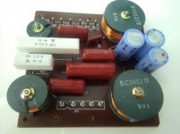
A picture of the SB-10 crossover, with the 3 electrolytic caps in blue.
I guess those are not air coils?
IMG_20180207_125459.jpg
I guess those are not air coils?
IMG_20180207_125459.jpg
Attachments
The controls may not come apart without damage, but they be an 'open' type construction that allows a suitable cleaner to be used.
If they were a bit noisy and intermittent, and if you normally 'set and forget' then they could be replaced by fixed resistors to make up a standard L pad attenuator.
There is no real problem with noise being picked up because all the impedances are (in the scheme of things) so low.
Those look like ferrite cores with the number such as 682 and 471 being the value in micro Henry's. The last number indicates the number of zeros to add.
So 682 = 6800uH or 6.8 milli Henry. 471 would be 470uH or 0.47 milli Henry.
The idea that you can restore the original sound of an almost 40 years old speaker, or to even improve it, is foolish.
There are many parts that age, and some you can't swap with newer ones.
The electrolytic caps change value over time, so replace them with the same type. You won't improve anything with an expensive film cap in the place of an electrolytic. Apart from that I won't change anything in the crossover, film caps, resistors and coils don't age, and changing them with "better" parts without really knowing what you're doing, and without measurements, is not a good idea.
The level controls probably need to be cleaned.
Unfortunately spiders and suspensions age, and you can't change them easily. And I don't even want to think about the magnets.
I hope you paid very little for the speakers, because for the 1800 Euro I have seen frankly there are far better sounding options.
Ralf
Thanks Gentlemen.
I did try to get an attenuator out today, Mooly, but I should have tried before I put the bass back in because it needed a push from the inside, so that will have to wait to next time. They appear to operate correctly no nose when turned with the music playing. I think they are a sealed unit as I have seen photos of them.
I take your point giralfino and after a week of looking at capacitor options I am not a lot wiser as to what to use. That is why I came to this forum in the hope someone else had done so experimenting with these speakers already. They really don't sound that bad, much as I always remember them being, a fairly realistic sounding speaker with out added tonality if that is the correct term, they sound much the same as the ones I got in 1981, must have been some of the better built gear of that time. Don`t worry giralfino I paid around half of 1800 Euros for them and the amp
Back to capacitors I have come across two other people on the net, one in Japan and one in France who replaced the 47uF with a large foil cap and claimed an improvement.
I think I will have to leave the two 330uF electrolytics caps as I can not see a way around the high uF value. I will just put new electrolytics in there,
I would also like to replace the polyesters that are in the signal path with something better to see if I can get a clearer sound, will longer leads be a problem? as I think they will have to be mounted out board style.
There are options that don`t seem overly expensive so I think I will start out with lower cost parts to prove if I am on the right track or not. I really need to start looking at the amp, now, I hope that is not going to be so confusing, although I suspect it might be
After 30+ years the original electrolytic caps are surely way out of specs. So replacing the 47uF old bipolar cap with a new film type effectively restore the original capacitance. You should notice the difference as the crossover will work differently in the two cases. But inserting a new 47uF bipolar cap does the same, at a fraction of the price. If someone claims to hear a difference between a new bipolar and a film cap of the same value, I suspect this is only a psychological effect, and a double blind test will fail.Back to capacitors I have come across two other people on the net, one in Japan and one in France who replaced the 47uF with a large foil cap and claimed an improvement.
So I suggest you to replace only the electrolytic caps with some new equivalent ones. All else is IMHO a waste of money and time.
Don't hold a breath on that, you simply can't remember the sound from 30+ years ago, and Technics wasn't a high end maker anyway.they sound much the same as the ones I got in 1981, must have been some of the better built gear of that time.
Second hand shopping can bring big saves, but only for recent gear. Vintage is only for sentimental reasons, performance wise there is no game with good engineered recent items at the same price.
Ralf
I would agree with most of what giralfino says regarding the caps. You could always try two 1200uF or 1500uF series caps to make a 600uF or 750uF bi-polar which are both right in the ball park.
Heat is the big killer of caps in an amp and so any that are in locations that run hot would be suspect. Age can be a problem but that said I have stuff from the mid to late 70's that is all original and in perfect working order.
If you want to change all the electrolytics in an amp then be 100% certain you know the value and orientation of each before removing them. Its easy to get confused when you have removed 30 or 40 caps and then start thinking erm, right then
If the pots on the speakers are OK and there are no 'dead' spots and so on as they are slowly rotated then just leave them be.
Do you have a favorite make as the original ones are no longer available?
Is it the same with the amps, ie just need to replace the eletrolytics, are there other parts that may need replacing? have just been searching the part numbers and not much is coming up
My advice for what its worth would be to always go for reputable well known commercial brands and not 'boutique' offerings. Look for 105C temperature rating for new electrolytics. And always buy from recognised companies who are the authorised distributers for the brands concerned.
Semiconductors don't wear out as such... resistors are the same unless they are underrated and running hot, which is common in a lot of equipment actually. These can usually be spotted by looking for discolouration on the resistor and board.
Hi eriksquires, Yes I have seen the Axon caps and noted they are a slightly smaller size than many of the others, might be good if space is restricted.
I haven`t made any decisions yet as what to do cap wise yet.
Today I have the amp open. I am a little concerned that is giving a smell off during use, I had changed the voltage setting to 220v instead of the 110v that it was set at it came from over the seas, maybe it is something to do with that they do run hot anyway and it is about 35C here to start with.
I am having a close visual inspection and have noticed what appears to be some leaking from the base of two large capacitors, what do you guys think?
IMG_20180208_132351[1].jpg
Attachments
![IMG_20180208_132351[1].jpg](/community/data/attachments/602/602590-af55113ce736f77a1fa862b61913217c.jpg)
That's the glue for keeping 'em firmly attached !
About caps, is 47 uF the one in series with the midrange ? ( on the schematics it was 12+8=20 uF )
I'm a little bit skeptik about differences between film and electros in that position, because the magnitude of distortion introduced is so little compared to speaker's distortion.
But a film one usually is better.
I wouldn't use a polarized one ( or two in series...thou a polarized one is effectively obtained by having two in series in the same "container" ! )
- Home
- Loudspeakers
- Multi-Way
- Technics SB-10 Crossover Questions