The TM will be based on the 4 ohm. The floorstander will be both 4 and 8 ohm SB17. I had to take a summer class to graduate on time, so I'm just determined to go through the class as fast as I can and finish early. Plan to be finished by next weekend. Soon as I am, I'm going to listen to two prototypes with different ctc spacing. Once I'm confident in my decision there I'll be able to make a lot of progress the rest of the summer.
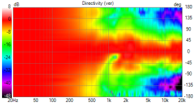
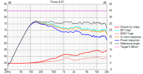
This is my current testing with VituixCad for my 2 way using Hypex FA122, B&C 8NDL51 and SB26ADC in 8" waveguide. Not perfect but getting there. Crossover 1.2khz LR 4th, the SB is one robust tweeter. I'm really enjoying listening in mono, its going to be strange going back to stereo once both are built.
Attachments
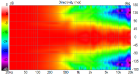
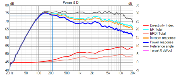
It looks like you didn't compensate for the mass roll off of the driver in the waveguide so the onaxis and everything else is dropping off above 10K. Maybe this was intentional or not. A first order filter from 10K or above usually compensates this and flattens the response out. I would also try to avoid a power response peak between 2 and 3K.
Have a look at the before and after here and see what you think ")
https://www.audiosciencereview.com/.../revel-m105-copy-diy-build.29465/post-1030095
The power peak is something I avoid due to liking 80's rock music, as most of the tracks were mixed on monitors with a power dip and any peak there sounds horrible.
https://www.audiosciencereview.com/.../revel-m105-copy-diy-build.29465/post-1030095
The power peak is something I avoid due to liking 80's rock music, as most of the tracks were mixed on monitors with a power dip and any peak there sounds horrible.
From Lipshitz and Vanderkooy, add some Iron Maiden and less is definately audible.Again, I can't see how a 2db power response peak is going to be audible, maybe im wrong
Yes you ideally want a smooth progression down without any peaks, it maybe difficult because the directivity is dropping at that point, the on axis is relatively flat and it is quite a way from the crossover point. It may be worth trying a small on axis dip in that region to smooth out the power and trial it both ways to see what you like best. Generally if EQ damages the on axis but makes everything else better it is a good trade, if you are listening out into the room and not close in.
You definitely should be able to hear a >2dB broadband dip in direct & fast comparison. Maybe try a more broadband music signal (electrical guitar is great for that) or just for checking if everything is ok pink noise. Also maybe go closer to the speaker and there should be a quiet environment of course.I tried the on-axis dip to flatten the power response, I couldn't really hear much of a difference, the total SPL difference (highest and lowest spl) is 2.3db, power response is around 2.7db variation or +-1.35 which is good enough for me!
Erin reviewed the Philarmonic Ceramic Mini, using -what I suspect- is using the SBAcoustics SB26CDC-C000-4 and the 5″ SB15CAC30-4
and check those distortion plots!
Imagine a small (sealed) bookshelf with the same drivers plus an @augerpro waveguide to help the directivity and performance at the XO, and you have a killer speaker! (to use it with 1+ SW of course).
https://www.erinsaudiocorner.com/loudspeakers/philharmonic_ceramic_mini/
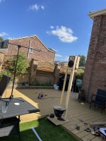
Indeed! I'll be listening to my prototypes later today as a matter of fact! Comparing two different ctc spacings, so I have confidence to move forward. Maybe @bikinpunk can chime in if he has ever measured a speaker with a narrow vertical sweet spot that caused him an issue in actual use. Assuming the speaker otherwise measured well of course.
monty6400,
I am not familiar with the process, but I had my WGs printed with MJF, and it came out well.
https://www.diyaudio.com/community/...uides-for-cnc-3d-printing.318190/post-7318610
When I was doing doing research on the Internet on what 3D printing material to use, I read that that HP did a lot of work in standardizing the MJF additive process, and most 3D printing houses are using HP printers, and the quality is more uniform from source to source.
- Home
- Loudspeakers
- Multi-Way
- Open source Waveguides for CNC & 3D printing!