Hi Brandon,
Yes. I'm actually running respective simulations. Results indicate, that minimizing the gap between HT-suspension and waveguide throat is the key here.
I'm considering to look at JBL-like 'diffractions slots' as well, as shown by Patrick. I'll come back with simulation results.
by crease are you referring to the Revel pic above?
Yes. I'm actually running respective simulations. Results indicate, that minimizing the gap between HT-suspension and waveguide throat is the key here.
I'm considering to look at JBL-like 'diffractions slots' as well, as shown by Patrick. I'll come back with simulation results.
That looks pretty good.
Thanks! I still realized a small error in this simulation and consequently set up a new one.
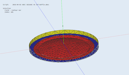
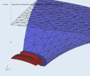
Geometry of HT membrane, suspension and 'gap' to the WG throat were refined:

This is still the elliptical WG VarC.
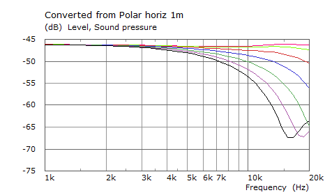
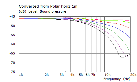
The respective simulation of the horizontal SPL under different angles from 0°-60° (10°-steps) in an infinite baffle:

Again for comparison the measurement, elliptical WG VarC, 0°-60°:

I think that's pretty close and a good starting point for refinements of the adaption of tweeter to WG-throat. I'll start to evaluate the 'crease' or diffraction slot from here.
A first result...
Identical elliptical waveguide and membrane geometry as shown in the last simulation above (#63), just with a 2mm-diffraction slot (or 'Revel-crease'), i.e. membrane is shifted 2mm back and there is a straight 2mm-step (yellow) up to the waveguide-throat:

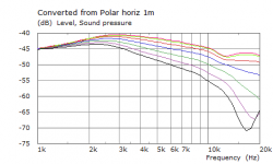
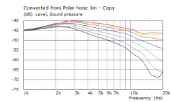
The respective SPLs under angles from 0° to 60°, 10°-steps:

A signifikant improvement. The dip around 13kHz on axis and up to 30° is almost gone. The dip around 18-20kHz present under higher angles (50° and 60°) with the membrane placed at the WG throat is almost gone as well, just a hint at 60° is still visible.
A step forward from my point of view. However, radiation still narrows up to 20kHz:

May be a 'phase shield' will help here. Next steps...
Identical elliptical waveguide and membrane geometry as shown in the last simulation above (#63), just with a 2mm-diffraction slot (or 'Revel-crease'), i.e. membrane is shifted 2mm back and there is a straight 2mm-step (yellow) up to the waveguide-throat:
The respective SPLs under angles from 0° to 60°, 10°-steps:
A signifikant improvement. The dip around 13kHz on axis and up to 30° is almost gone. The dip around 18-20kHz present under higher angles (50° and 60°) with the membrane placed at the WG throat is almost gone as well, just a hint at 60° is still visible.
A step forward from my point of view. However, radiation still narrows up to 20kHz:
May be a 'phase shield' will help here. Next steps...
I like the result, but was it from the crease or the membrane shifted back? I've done a number of measurements using shims to set the membrane back in the PETT thread. IIRC there was degradation for the smaller 5" waveguides for all shims, but the larger 8" looked best with a .03" shim, worse smaller or larger than that.
Hi,
Just an update on the simulations around the 'Revel-Areas' or 'step' at the waveguide throat, i.e. alignment of a specific dome geometry to a waveguide throat. I did some simulations and posted result in detail in the waveguide thread over in the German DIY-forum.
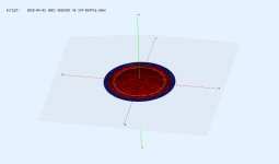
Let's see. The last simulations have been performed based on this image of the SB26ADC in the WG-throat:

The resulting simulation of the horizontal SPL under different angles matched pretty well with the measured horizontal radiation (see post #63).
Simulation with a membrane (dome) perfectly fitting to the WG-throat (i.e. no gap between suspension and WG-throat) looked significantly better and suggested, that the gap significantly contributes to the dip around 13kHz and around 18-20kHz under higher angles (see post #55).
I give the horizontal SPL from 0°-60° here for comparability, as I missed to do that in post #55.
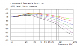
Full membrane:

Horizontal SPL 0°-60°:

Avoiding or at least minimizing the 'gap' between the tweeter suspension and WG-throat would obviously improve the horizontal radiation. However, as ist is difficult to avoid any gap between tweeter suspension and WG-throat in reality, it is worth to evaluate how to deal with this. In fact there is a small gap between the SB26ADC suspension and the WG-throat.
As the simulation of the suggested 'Revel crease' or 2mm 'step' had a rather positive impact on the horizontal radiation of the elliptical waveguide VarC, I did some additional simulations in order to better understand the observed improvement caused by the 2mm-step (i.e. 2mm shift of the SB26ADC membrane back from the WG-throat, see simulation).
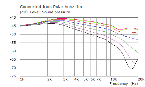
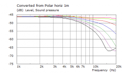
First of all a very basic check - the simulation of the 'SB26ADC-membrane' in an infinite baffle:

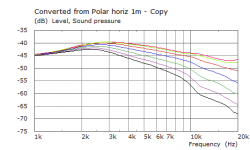
SPL horizontal 0°-60°:
As expected, directivity increases with higher frequencies because of the diameter of the radiation source. The dips between 18-20kHz under higher angles are seen here again, obviously caused by the membrane diameter. To improve here needs either a smaller membrane (sound source) or kind of a diffraction device (phase shield...).
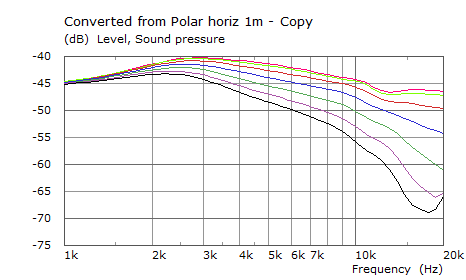
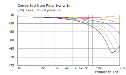
Now what happens if the 2mm step is added?
Same with 2mm-step...
The 'SB26ADC-membrane' in an infinite baffle with 2mm step:
SPL horizontal 0°-60°:
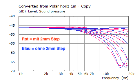
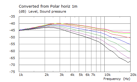
Not really a huge difference. See comparison/overlay of the two simulations (red = with, blue = without 2mm step):
Again, what happens with the SB26ADC-membrane in the elliptical WG and different steps then?
For simplification only the image of the simulation (i.e. SB26ADC membrane in elliptical WG VarC in infinite baffle with the membrane shifted back from the WG throat, different distances or 'steps'). I add the simulation without step (see post #63) for comparison.
0mm step:

0mm step, SPL horizontal 0°-60°:
-1mm step, SPL horizontal 0°-60°:
-2mm step, SPL horizontal 0°-60°:
-3mm step, SPL horizontal 0°-60°:

-5mm step in next post - upper limit of attachments...
Just an update on the simulations around the 'Revel-Areas' or 'step' at the waveguide throat, i.e. alignment of a specific dome geometry to a waveguide throat. I did some simulations and posted result in detail in the waveguide thread over in the German DIY-forum.
I like the result, but was it from the crease or the membrane shifted back?
Let's see. The last simulations have been performed based on this image of the SB26ADC in the WG-throat:
The resulting simulation of the horizontal SPL under different angles matched pretty well with the measured horizontal radiation (see post #63).
Simulation with a membrane (dome) perfectly fitting to the WG-throat (i.e. no gap between suspension and WG-throat) looked significantly better and suggested, that the gap significantly contributes to the dip around 13kHz and around 18-20kHz under higher angles (see post #55).
I give the horizontal SPL from 0°-60° here for comparability, as I missed to do that in post #55.
Full membrane:
Horizontal SPL 0°-60°:
Avoiding or at least minimizing the 'gap' between the tweeter suspension and WG-throat would obviously improve the horizontal radiation. However, as ist is difficult to avoid any gap between tweeter suspension and WG-throat in reality, it is worth to evaluate how to deal with this. In fact there is a small gap between the SB26ADC suspension and the WG-throat.
As the simulation of the suggested 'Revel crease' or 2mm 'step' had a rather positive impact on the horizontal radiation of the elliptical waveguide VarC, I did some additional simulations in order to better understand the observed improvement caused by the 2mm-step (i.e. 2mm shift of the SB26ADC membrane back from the WG-throat, see simulation).
First of all a very basic check - the simulation of the 'SB26ADC-membrane' in an infinite baffle:
SPL horizontal 0°-60°:
As expected, directivity increases with higher frequencies because of the diameter of the radiation source. The dips between 18-20kHz under higher angles are seen here again, obviously caused by the membrane diameter. To improve here needs either a smaller membrane (sound source) or kind of a diffraction device (phase shield...).
Now what happens if the 2mm step is added?
Same with 2mm-step...
The 'SB26ADC-membrane' in an infinite baffle with 2mm step:
SPL horizontal 0°-60°:
Not really a huge difference. See comparison/overlay of the two simulations (red = with, blue = without 2mm step):
Again, what happens with the SB26ADC-membrane in the elliptical WG and different steps then?
I've done a number of measurements using shims to set the membrane back in the PETT thread. IIRC there was degradation for the smaller 5" waveguides for all shims, but the larger 8" looked best with a .03" shim, worse smaller or larger than that.
For simplification only the image of the simulation (i.e. SB26ADC membrane in elliptical WG VarC in infinite baffle with the membrane shifted back from the WG throat, different distances or 'steps'). I add the simulation without step (see post #63) for comparison.
0mm step:
0mm step, SPL horizontal 0°-60°:
-1mm step, SPL horizontal 0°-60°:
-2mm step, SPL horizontal 0°-60°:
-3mm step, SPL horizontal 0°-60°:
-5mm step in next post - upper limit of attachments...
Attachments
-
 2018-04-05 SB26ADC Membrane Suspension V7 -2mm step in infinte baffle image 1.png67.9 KB · Views: 1,945
 -
 2018-04-05 SB26ADC Membrane Suspension V7 in infinte baffle image 1.png62 KB · Views: 1,955
 -
 2018-04-08 SB26ADC Membrane Suspension V7 -2mm step in infinte baffle SPL 0-60deg 2.png12.8 KB · Views: 1,936
 -
 2018-04-08 SB26ADC Membrane Suspension V7 in infinte baffle SPL horiz 0-60deg 2.png12.4 KB · Views: 1,956
 -
 2018-04-05 SB26ADC Membrane Suspension V7 mit vs ohne -2mm step in infinte baffle SPL 0-60deg 1.png21.1 KB · Views: 1,936
 -
 2018-04-03 elliptical WG VarC Membrane Susp V7 Gap2mm 1.png224.2 KB · Views: 1,958
 -
 2018-04-03 Elliptical WG VerC Membrane Susp V7 2mm Gap SPL 0-60deg 1k-20k 1.png14.7 KB · Views: 1,937
 -
 2018-04-12 elliptical WG VarC SB26 Membr V7 2mm gap -1mm diffr slot SPL 0-60deg 1.png15.1 KB · Views: 1,928
 -
 2018-04-06 elliptical WG VarC SB26 Membr V7 2mm gap -2mm diffr slot horiz SPL 0-60deg 1.png14.9 KB · Views: 1,944
 -
 2018-04-12 elliptical WG VarC SB26 Membr V7 2mm gap -3mm diffr slot SPL 0-60deg 1.png15.1 KB · Views: 1,926


")
Hi,
Just an update on the simulations around the 'Revel-Areas' or 'step' at the waveguide throat, i.e. alignment of a specific dome geometry to a waveguide throat. I did some simulations and posted result in detail in the waveguide thread over in the German DIY-forum.
Let's see. The last simulations have been performed based on this image of the SB26ADC in the WG-throat:
The resulting simulation of the horizontal SPL under different angles matched pretty well with the measured horizontal radiation (see post #63).
These attachments don't show up for me
Seems that the first there attachments do not show up. I attach again, hope it works now.
...
Let's see. The last simulations have been performed based on this image of the SB26ADC in the WG-throat:

The resulting simulation of the horizontal SPL under different angles matched pretty well with the measured horizontal radiation (please refer to post #63, not shown again here).
Simulation with a membrane (dome) perfectly fitting to the WG-throat (i.e. no gap between suspension and WG-throat) looked significantly better and suggested, that the gap significantly contributes to the dip around 13kHz and around 18-20kHz under higher angles (see post #55).
I give the horizontal SPL from 0°-60° here for comparability, as I missed to do that in post #55:
Full membrane:

Horizontal SPL 0°-60°:

Avoiding or at least minimizing the 'gap' between the tweeter suspension and WG-throat would obviously improve the horizontal radiation. However, as ist is difficult to avoid any gap between tweeter suspension and WG-throat in reality, it is worth to evaluate how to deal with this. In fact there is a small gap between the SB26ADC suspension and the WG-throat.
As the simulation of the suggested 'Revel crease' or 2mm 'step' had a rather positive impact on the horizontal radiation of the elliptical waveguide VarC, I did some additional simulations in order to better understand the observed improvement caused by the 2mm-step (i.e. 2mm shift of the SB26ADC membrane back from the WG-throat, see simulation).
....
Next see post #67 - goes on with the SB26ADC membrane in an infinite baffle without WG.
...
I like the result, but was it from the crease or the membrane shifted back?
Let's see. The last simulations have been performed based on this image of the SB26ADC in the WG-throat:
The resulting simulation of the horizontal SPL under different angles matched pretty well with the measured horizontal radiation (please refer to post #63, not shown again here).
Simulation with a membrane (dome) perfectly fitting to the WG-throat (i.e. no gap between suspension and WG-throat) looked significantly better and suggested, that the gap significantly contributes to the dip around 13kHz and around 18-20kHz under higher angles (see post #55).
I give the horizontal SPL from 0°-60° here for comparability, as I missed to do that in post #55:
Full membrane:
Horizontal SPL 0°-60°:
Avoiding or at least minimizing the 'gap' between the tweeter suspension and WG-throat would obviously improve the horizontal radiation. However, as ist is difficult to avoid any gap between tweeter suspension and WG-throat in reality, it is worth to evaluate how to deal with this. In fact there is a small gap between the SB26ADC suspension and the WG-throat.
As the simulation of the suggested 'Revel crease' or 2mm 'step' had a rather positive impact on the horizontal radiation of the elliptical waveguide VarC, I did some additional simulations in order to better understand the observed improvement caused by the 2mm-step (i.e. 2mm shift of the SB26ADC membrane back from the WG-throat, see simulation).
....
Next see post #67 - goes on with the SB26ADC membrane in an infinite baffle without WG.
Thanks Christoph. I'll tighten up the fitment in the next designs. So if I understand correctly, the major improvements to the simmed response are due to: tight dome fitment, and a small 2-3mm step? Where does the crease fit into this? I'm wrestling with Fusion 360 to design that crease, I may just take my Japanese chisels after one I have and measure the results as a quicker way to get some data.
I'm going to send another batch of designs to the printer soon, with more of the larger guides included. Also have the new Dayton RS28A on the way.
I'm going to send another batch of designs to the printer soon, with more of the larger guides included. Also have the new Dayton RS28A on the way.
Hi Brandon,
My take of the simulations so far: Yes, no gap between the dome/suspension improves the situation - though it will probably not possible to achieve the ideal situation in real live. Still, tighten up the fitment will certainly help.
The step or crease (the 2-3mm for the simulated tweeter) helps, if we have to accept the 'gap' between suspension and waveguide throat. So far I think that the best height of the step (2-3mm in the simulation) depends on (i) the geometry, e.g. height of the dome, (ii) the size of the 'gap' and (iii) the waveguide contour. This means, that the right step height has to be adjusted to a specific tweeter (dome and suspension geometry, the existing gap to the WG throat and the specific waveguide.
Before you print new versions, could you possibly measure the exact height of the SB26ADC dome so I can check back, if my simulation was exact enough? You could simply build the step (or crease) using the existing waveguide VarC and add shims with the correct diameter between tweeter and throat, as you did before.
I'm as well not sure, if the 'step' or crease as simulated is already the best solution. May be a more smooth rounding of the edge (like done in oblate spheroid WGs) work better. I'll simulate this.
However, I think it is good to minimize the gap between membrane/Suspension and WG throat AND to start the WG contour perpendicular to the membrane.
Some simulations to look at that: First a simulation of a flat membrane without gap between membrane and WG throat in the elliptical WG VarC, with and without the 2mm 'step' or crease.
Flat membrane in elliptical WG VarC, no step:

SPL 0°-60°:

Though there is no gap between membrane and WG throat, we still see the 13kHz and 18-20kHz dips.
Does the 2mm 'step' or crease help here?
Flat membrane in elliptical WG VarC with -2mm step/crease:

SPL 0°-60°:

Note, that the situation did not improve basically, i.e. the positive effect of the 2mm step seen before, depends on the membrane geometry and gap to the WG throat.
What happens, if we use the elliptical WG VarC and simulate a membrane, which fulfills the suggested properties, i.e. (i) no gap to the WG throat and (ii) a membrane perpendicular to the contour at the WG throat?
This would look like this:

SPL 0°-60°:

Now, this looks promising. Thus I show the horizontal radiation normalized to 0° as well:

Obviously, we do not have the ideal dome geometry for the WG available.
However, I'd be happy to re-check m simulations with the exact dome/suspension geometry of the SB26ADC and then adjust the best 'Step' height or crease. I'd as well check, if the crease or somehow rounded version of the step works best.
Why did the step/crease work that well for the SB26ADC simulation? I'm not finally clear with that, however, I suspect that the step (bringing the membrane 2mm back) brings the WG contour 'in line' with the emitting dome/suspension, like indicated in this image:

However, this is just a speculation and has to be evaluated still. A simulation with verified dome/suspension contour (including the angle of the dome to the tweeter faceplate) and slightly adjusted WG contour (bringing the contour perpendicular to the dome) and respective step/crease might tell...
My take of the simulations so far: Yes, no gap between the dome/suspension improves the situation - though it will probably not possible to achieve the ideal situation in real live. Still, tighten up the fitment will certainly help.
The step or crease (the 2-3mm for the simulated tweeter) helps, if we have to accept the 'gap' between suspension and waveguide throat. So far I think that the best height of the step (2-3mm in the simulation) depends on (i) the geometry, e.g. height of the dome, (ii) the size of the 'gap' and (iii) the waveguide contour. This means, that the right step height has to be adjusted to a specific tweeter (dome and suspension geometry, the existing gap to the WG throat and the specific waveguide.
Before you print new versions, could you possibly measure the exact height of the SB26ADC dome so I can check back, if my simulation was exact enough? You could simply build the step (or crease) using the existing waveguide VarC and add shims with the correct diameter between tweeter and throat, as you did before.
I'm as well not sure, if the 'step' or crease as simulated is already the best solution. May be a more smooth rounding of the edge (like done in oblate spheroid WGs) work better. I'll simulate this.
However, I think it is good to minimize the gap between membrane/Suspension and WG throat AND to start the WG contour perpendicular to the membrane.
Some simulations to look at that: First a simulation of a flat membrane without gap between membrane and WG throat in the elliptical WG VarC, with and without the 2mm 'step' or crease.
Flat membrane in elliptical WG VarC, no step:
SPL 0°-60°:
Though there is no gap between membrane and WG throat, we still see the 13kHz and 18-20kHz dips.
Does the 2mm 'step' or crease help here?
Flat membrane in elliptical WG VarC with -2mm step/crease:
SPL 0°-60°:
Note, that the situation did not improve basically, i.e. the positive effect of the 2mm step seen before, depends on the membrane geometry and gap to the WG throat.
What happens, if we use the elliptical WG VarC and simulate a membrane, which fulfills the suggested properties, i.e. (i) no gap to the WG throat and (ii) a membrane perpendicular to the contour at the WG throat?
This would look like this:
SPL 0°-60°:
Now, this looks promising. Thus I show the horizontal radiation normalized to 0° as well:
Obviously, we do not have the ideal dome geometry for the WG available.
However, I'd be happy to re-check m simulations with the exact dome/suspension geometry of the SB26ADC and then adjust the best 'Step' height or crease. I'd as well check, if the crease or somehow rounded version of the step works best.
Why did the step/crease work that well for the SB26ADC simulation? I'm not finally clear with that, however, I suspect that the step (bringing the membrane 2mm back) brings the WG contour 'in line' with the emitting dome/suspension, like indicated in this image:
However, this is just a speculation and has to be evaluated still. A simulation with verified dome/suspension contour (including the angle of the dome to the tweeter faceplate) and slightly adjusted WG contour (bringing the contour perpendicular to the dome) and respective step/crease might tell...
The step or crease
Now I understand the confusion. The step and crease are different things. The crease I'm referring to is in the pic of the Revel speaker, running vertically along the horn wall. It is very slight, I hadn't noticed it before until it was pointed out.
In earlier testing I assume a wall meeting essentially normal to the diaphragm (perpendicular as you put) would be ideal, but I found steep walls to be generally better.Probably for other reasons related to wavelength vs curve radius of the wall, and whether the flare meets tangent to the baffle surface or not. I can always revisit it though with the large guides.
Now I understand the confusion. The step and crease are different...the crease...is in the pic of the Revel speaker...
I was also a bit confused, but could you post the picture?
Best wishes
David
Sorry for the confusion. I may have described things a bit complicated and unclear as a non-native speaker.
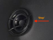
When I'm talking 'step' I refer to the step developing, when I set back the membrane relative to the waveguide throat (here colored yellow):

Though the Revel-'crease' is a bit rounded at the transition to the waveguide contour, I suspect that the depths of the Revel-'crease' is roughly in the same range as the 2mm 'step' used for the elliptical waveguide - and does basically the same, i.e. improve radiation.
Yes, with the crease I referred as well to the image of the Revel speaker.Now I understand the confusion. The step and crease are different things. The crease I'm referring to is in the pic of the Revel speaker, running vertically along the horn wall. It is very slight, I hadn't noticed it before until it was pointed out.
When I'm talking 'step' I refer to the step developing, when I set back the membrane relative to the waveguide throat (here colored yellow):
Though the Revel-'crease' is a bit rounded at the transition to the waveguide contour, I suspect that the depths of the Revel-'crease' is roughly in the same range as the 2mm 'step' used for the elliptical waveguide - and does basically the same, i.e. improve radiation.

Hi,
A series of new simulations, again around the 'step', i.e. height between tweeter membrane and waveguide-throat.
I did two more changes for this series of simulations, (i) did a slight change to the horizontal waveguide contour and (ii) refined the membrane geometry according to data received from Brandon.
The circle sector used as profile for the waveguide contour was replaced by a spline-profile in order to be more flexible during the profile optimization process to be done later. The horizontal profile used during these simulations looks like this (the vertical profile as not changed at this stage):

The SB26ADC membrane geometry used for these simulations looks like this:

The image is somehow self-explanatory. The 'step' (yellow) is varied from 0mm to 5mm.
A summary of the simulations is given in the next image:

Images at the left side show horizontal radiation normalized to 0°, images at the right side show the SPL at different angles from 0° to 60° in 10°-steps for steps from 0mm to 5mm.
Again - as simulated for the elliptical waveguide typeC with the somehow simpler SB26ADC membrane geometry before - the 2mm-step seems beneficial for a smooth (although not real constant) directivity.
More on waveguide-throat variants and phase-shield / phase-plug variants later.
A series of new simulations, again around the 'step', i.e. height between tweeter membrane and waveguide-throat.
I did two more changes for this series of simulations, (i) did a slight change to the horizontal waveguide contour and (ii) refined the membrane geometry according to data received from Brandon.
The circle sector used as profile for the waveguide contour was replaced by a spline-profile in order to be more flexible during the profile optimization process to be done later. The horizontal profile used during these simulations looks like this (the vertical profile as not changed at this stage):
The SB26ADC membrane geometry used for these simulations looks like this:
The image is somehow self-explanatory. The 'step' (yellow) is varied from 0mm to 5mm.
A summary of the simulations is given in the next image:
Images at the left side show horizontal radiation normalized to 0°, images at the right side show the SPL at different angles from 0° to 60° in 10°-steps for steps from 0mm to 5mm.
Again - as simulated for the elliptical waveguide typeC with the somehow simpler SB26ADC membrane geometry before - the 2mm-step seems beneficial for a smooth (although not real constant) directivity.
More on waveguide-throat variants and phase-shield / phase-plug variants later.
- Home
- Loudspeakers
- Multi-Way
- Open source Waveguides for CNC & 3D printing!