...what do you take into account for the choose of your waveguide size on a project (aside from geometric constrains) ? Point of crossover ? Directivity match between driver ? Sensitivity ?
Good questions! My thoughts:
- If sensitivity is important for your design, don't count on the waveguide to help you (much). Sensitivity should be flat up to about 10kHz or 20 kHz, where the waveguide will have very little effect. For lower frequencies, the xover will have to attenuate the sloped response resulting from the waveguide, which will "undo" the apparent sensitivity gain by the waveguide.
- Point of xover: sure, that's always important. It depends on the drivers used, on the loudspeaker concept as a whole, etc. The waveguide should blend in to these constraints.
- Matching directivity: this is where waveguides get interesting! Smooth controlled directivity, or even constant directivity, throughout most of the midrange and treble range will make a HUGE difference in the sonic results!
In the end, the criteria for a waveguide will depend on your design criteria for the speaker as a whole. With the Open Source Monkey Coffin for example, the midrange driver was set, and we were looking to extend this with a matching tweeter. A WG148 waveguide resulted in nicely controlled directivity with a smooth transition from the mid to the tweeter. The augerpro waveguide for the OSMC was modeled along the WG148 geometry, but provides a better fit/mount to the Scan tweeter (and has a much nicer look and feel).
Thx for this detailed answer !
I suspected that directivity was the answer. Regarding this subject, another beginner question. The "smoothness" of the directivity in the crossover region is logical for me. But the choice between a narrow and a wide directivity is not so obvious for me. I suppose that wide means more room interactions and narrow means a smaller sweetspot ?
Narrow may be obtained with a large midrange (6 or 8 inches) and large waveguide (+narrow radiation angle) crossed around 1.5 kHz ? (Adapted to big room and far listening spot ?)
Wide may be obtained with a small midrange (2 or 3 inches) and a small waveguide (wide radiation angle) crossed around 2.5 kHz ? (Adpated to close listening spot ?)
Am I wrong ? Be gentle with me, I am only in the understanding phase of diy project (I have allready built a speaker with a friend but it was troels design so no need to overthink). Maybe I should start doing simulation with a software... (Any suggestion for the software is welcomed)
Hello Brandon,Thanks, there a little problem, on this Step and also on the 6" Step on the websiste, it cannot be open by either AB Viewer or STP Viewer, in the case of STP viewer the software bug with a critical error, AB viewer show nothing on his side.
No problems for the 6.5" version, that works perfectly ^^
I will try other soft for investigate.
Just tried to open the 6" step version with some issues in the wireframe : looks like there is a doubled outline on this file, located at the junction of the waveguide and the flat face.
Do you see the same problem in your modeling software?
Thx for your help
[emoji4]
Hi,
There it is. All pictures deal with the 6" version (sb26), step files.
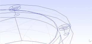
First picture is the file loaded with freecad 0.18. I tried to fix the flat face, after removing it you can see on picture 2 what i explained in my last post.
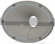
I tried to open it in Fusion360, and export it back to freecad always in step format. This time the file opens correctly in freecad, but still some issues as you can see on picture 3.
Hope this helps [emoji4]


There it is. All pictures deal with the 6" version (sb26), step files.
First picture is the file loaded with freecad 0.18. I tried to fix the flat face, after removing it you can see on picture 2 what i explained in my last post.
I tried to open it in Fusion360, and export it back to freecad always in step format. This time the file opens correctly in freecad, but still some issues as you can see on picture 3.
Hope this helps [emoji4]
The resolution that circles and arcs are displayed at in most cad programs, FreeCAD Included can be changed, as you zoom in you notice that the circle is a polyline. It's display related not geometry related. Keeping it low helps to refresh the screen quicker with changes.
That's what I see in your second and third images.
That's what I see in your second and third images.
You'r talking about CAD visual resolution representation, and it' not happen on the 6.5" Step :
This kind of things happen when geometrically the surface (or the volume/bodies after this) haven't the same edge, like it's two different volume stick together but not "sharing" the edge, sometime there is a gap, sometime the two edge overlaps without merging.
Whatever the visual resolution representation in CAD software, a shared edge between two volumes or surfaces has never a gap or a overlaps, even in STL format (3D printer will do strange things other wise).
So present problems could come from how the 6" model is design, export, or if the Step come from a STL (Step must come from original format), but I don't thinks augerpro does this.
It can be a different way to design the 6" (unchecked merge when creating volume or something like this), it can also be the export also, by default in Step export all surfaces/volumes is exported in geometric but you can change it to wireframe and/or to not export some faces/bodies.
First picture tend to show that this hypothesis could be valid, so with a miss-click it will miss a surface or a edge that other CAD (but not the STEP viewer that will fail) will try to recover, as CAD software launch a optional functions recognition after opening a Step.
The last picture can be Fusion360 trying to recover edge to not merged volumes, or a mix of everything , like if the elliptic shape is no longer a geometric shape but a mesh shape (truly not "only" in representation).
A Step that produce a fatal error in a Step viewer is not a good sign ^^ ,as the 6" step does but not the 6.5".
Step doesn't have a resolution itself, it's a ISO geometric format mainly design for lossless exchanges or transformations (like 2D vector format).
There is two Step format : STEP AP203 and STEP AP214, AP214 is a extension of AP203 that add color and layer, so may be it's just because it's a AP203 Step and not a AP214, but I have try to re-export 6.5" Step to Step AP203 and I can use it again in his original geometric shape.
But a re-export, just in case of, of the 6" in STEP AP214 (geometrics, not wireframe, it will fail) from the original could solve the problems, a check of the front plate and elliptic volume/bodies too, about merging volumes.
STL is a format that is a 3D mesh faceting representation of a geometric representation thanks to a parametric resolution, that is usually generated from the proprietary format (Fusion360/SolidWroks,AutoCad...) or... from a Step file
Sorry for the long post, I have try to write it for have to a common understanding ^^
This kind of things happen when geometrically the surface (or the volume/bodies after this) haven't the same edge, like it's two different volume stick together but not "sharing" the edge, sometime there is a gap, sometime the two edge overlaps without merging.
Whatever the visual resolution representation in CAD software, a shared edge between two volumes or surfaces has never a gap or a overlaps, even in STL format (3D printer will do strange things other wise).
So present problems could come from how the 6" model is design, export, or if the Step come from a STL (Step must come from original format), but I don't thinks augerpro does this.
It can be a different way to design the 6" (unchecked merge when creating volume or something like this), it can also be the export also, by default in Step export all surfaces/volumes is exported in geometric but you can change it to wireframe and/or to not export some faces/bodies.
First picture tend to show that this hypothesis could be valid, so with a miss-click it will miss a surface or a edge that other CAD (but not the STEP viewer that will fail) will try to recover, as CAD software launch a optional functions recognition after opening a Step.
The last picture can be Fusion360 trying to recover edge to not merged volumes, or a mix of everything
, like if the elliptic shape is no longer a geometric shape but a mesh shape (truly not "only" in representation).A Step that produce a fatal error in a Step viewer is not a good sign ^^ ,as the 6" step does but not the 6.5".
Step doesn't have a resolution itself, it's a ISO geometric format mainly design for lossless exchanges or transformations (like 2D vector format).
There is two Step format : STEP AP203 and STEP AP214, AP214 is a extension of AP203 that add color and layer, so may be it's just because it's a AP203 Step and not a AP214, but I have try to re-export 6.5" Step to Step AP203 and I can use it again in his original geometric shape.
But a re-export, just in case of, of the 6" in STEP AP214 (geometrics, not wireframe, it will fail) from the original could solve the problems, a check of the front plate and elliptic volume/bodies too, about merging volumes.
STL is a format that is a 3D mesh faceting representation of a geometric representation thanks to a parametric resolution, that is usually generated from the proprietary format (Fusion360/SolidWroks,AutoCad...) or... from a Step file
Sorry for the long post, I have try to write it for have to a common understanding ^^
Yes I was because FreeCAD defaults to a low level and if you draw a circle and zoom in it looks just like those images.You'r talking about CAD visual resolution representation, and it' not happen on the 6.5" Step :
I can see the point you are making about the differences between the 6 and 6.5 versions when I open them in gmsh.
In the 6.5 (right image) version the top elipse that joins the waveguide profile is a single profile.
In the 6 (left image) version there are two separate edges creating that odd gap.
You can see it where the dotted grey line that represents the profile meets the ellipse(s) in the middle of the images.
It's the opposite way round where the back thicker sections meets, in the 6 it is one profile and in the 6.5 it is two. Not that it really matters in that location though.
Attachments

Last edited:
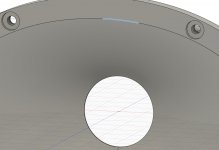
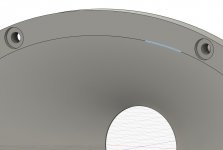
I opened the .step in F360 and nothing seems wrong to my eyes. Zebra analysis is ok. If i zoom in on that seam you can see the curve go to straight lines, but that is just the visual rendering as mentioned above. Opening the .stl to look inside the model I see not issue at that seam. Attached is a pic. You would see an internal surface drop down vertically from that seam if there was an issue.
I wish I had a better answer, clearly the different softwares behave differently and some suggest a problem where there is none, but what can I do about that? All I can say is that they print fine for me and my slicer never has an issue.

I wish I had a better answer, clearly the different softwares behave differently and some suggest a problem where there is none, but what can I do about that? All I can say is that they print fine for me and my slicer never has an issue.
You could see it in fusion when the outline of the elipse was selected. On the 6 inch version the polyline is on top. In the 6.5 the elipse is split but represents what you intended.
Attachments
Last edited:
Brandon it looks the same to me.
It seems like the top surface where the mounting holes are is using an elipse as it selects as a face. The edge of the waveguide still selects as a polyline which is what was shown in gmsh.
It seems like the top surface where the mounting holes are is using an elipse as it selects as a face. The edge of the waveguide still selects as a polyline which is what was shown in gmsh.
Attachments

Removing the two separate lines and only having one should fix any boundary related issues that might throw an error.
My point with what you changed is that you ended up with the polyline and not the section of ellipse that comes out in the 6.5 version. Meant as an observation not a criticism
My point with what you changed is that you ended up with the polyline and not the section of ellipse that comes out in the 6.5 version. Meant as an observation not a criticism
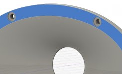
I found what caused this, although I still have no idea why .stl meshing would have no problem and .step would. Attached are updated .step files
Thanks you did it
, the ellipse is now geometric, I can now work on it now for aznowiczfluid> ok, the software angle for processing these files isn't something I know terribly well so I wasn't sure if I was following your comments. Thanks
NicoB> no problem. If anyone see something similar let me know. I'm going to go through all of the files on my website as soon as I get some T25B testing done, to make sure I didn't accidently skip the step that caused this issue.
NicoB> no problem. If anyone see something similar let me know. I'm going to go through all of the files on my website as soon as I get some T25B testing done, to make sure I didn't accidently skip the step that caused this issue.

I'll let you know,Now that's interesting! Wonder what the polars will look like.
Next step is to measure acoustic offset with the mid to cut this shape properly. For sure, answer is to be given... in 2021!
- Home
- Loudspeakers
- Multi-Way
- Open source Waveguides for CNC & 3D printing!