Hi Brandon,
Hi Ro808,
Christoph
Will do so. Try to do it during the next weekend and will come back with results soon.Christoph> if you get a chance, work the sim more on the SB26ADC. Of interest: a shim at the throat to move the dome back, vertical wall radius, and to a lesser extent the horizontal wall radius - though I feel that is pretty right on.
Hi Ro808,
I'm not sure if I get your idea. Could you possibly give a rough drawing of the profile you are suggesting with rough dimensions? This will help for a simulation.Christoff, if it's not too much of a hassle, it would be interesting to see the effect of a small area of "low curvature" (or even flat) in a (rather deep) waveguide for a hemispherical dome tweeter.
Some space of 2-4mm around the surround "to breath" > might eliminate/cancel interferences.
Christoph
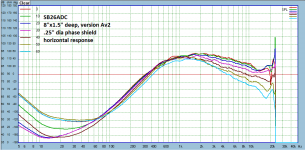
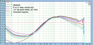
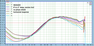
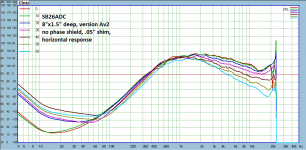
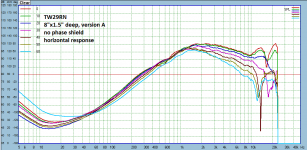
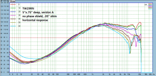
Here are the results for SB26ADC on the 8" waveguide. Note, I usually measure with and without phase shield, sometimes with a shim between mouth and tweeter, and sometimes check vertical responses on more promising/new designs. All of this is noted in the screenshot.
Attachments
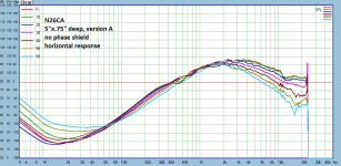
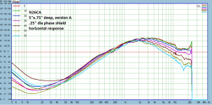
Much awaited results on the Transducer Lab N26CA! Probably the best of the bunch on the troublesome 5" waveguide. I think the squiggle around 10khz is a similar to issues I had with the SB26, might just need a small lip and/or some tape on the mounting face to stop vibration. Wish these weren't NLA, moving up in size will probably make some beautiful plots.
Attachments
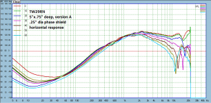
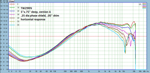
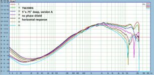
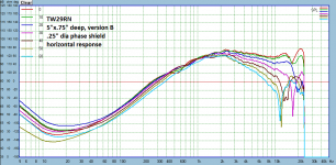
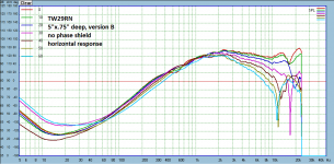
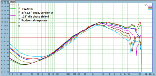
Here is the TW29RN on both 5" and 8" waveguides. With pinned center it's no surprise the phase shield does nothing. The top octave has me miserable. The difference version A and B is slightly different wall radius.
Attachments
Roland, Christoph> here some pics to show what I'd like to focus on (other than the ever present top octave dip in the on axis response so common in waveguides):


A couple posts back I mentioned the flawed phase shield. The support rod was off-center, and so the response was different when going off axis to one side or the other. Here are the plots going the opposite direction of F above, I *assume* the response with the fixed phase shield should be the average, if so, it should look real good:

BTW you can also see the ripple below about 4khz flip flop, so all that ripple is just the baffle diffraction.
A couple posts back I mentioned the flawed phase shield. The support rod was off-center, and so the response was different when going off axis to one side or the other. Here are the plots going the opposite direction of F above, I *assume* the response with the fixed phase shield should be the average, if so, it should look real good:
BTW you can also see the ripple below about 4khz flip flop, so all that ripple is just the baffle diffraction.
Brendon, apart from the issues >10kHz these look promising, especially the elliptical.
Could you post some pics of these last 2 waveguides with the SB26ADC mounted?
Just to check the throath area: the distance of the surround towards the walls, the height of the dome vs the surround vs. the waveguide.
Could you post some pics of these last 2 waveguides with the SB26ADC mounted?
Just to check the throath area: the distance of the surround towards the walls, the height of the dome vs the surround vs. the waveguide.
Can't remember why, but when I was experimenting with waveguides I thought a bigger gap would solve the top octave issue too.Christoff, if it's not too much of a hassle, it would be interesting to see the effect of a small area of "low curvature" (or even flat) in a (rather deep) waveguide for a hemispherical dome tweeter.


I finally did some more simulations of your 0.75'' deep elliptical waveguide version C. Simulation distance was always 1m.
I did a comparison of simulating the elliptical waveguide version C either in an enclosure...

...or in an infinite baffle:

The infinite baffle is plane to the waveguide mouth.
The normalized horizontal directivity plot for the waveguide place in an infinite baffle (upper half) or in the simple enclosure shown above (lower part):

Same for the vertical directivity:

The placement of a (shallow) waveguide in a specific baffle has a huge impact on its directivity below 4 kHz. The widening of radiation between 10 kHz and 13 kHz is (largely) independent from mounting of the WG in an infinite baffle or enclosure - but true for the horizontal and vertical radiation. As a next step I will have a look on this, why it happens and how to avoid it.
Reason for comparing radiation in an infinite baffle vs enclosure was to demonstrate, that it probably makes sense to (i) develop a waveguide for a specific enclosure and application and (ii) to keep effects of baffle edges and possible chamfers in mind.
Which baffle width would be preferable for the elliptical waveguide, i.e. combination with a 6'' or 8'' mid woofer?
Hi Pallas,
Thanks for pointing out the step/crease seen at the throat of the Revel'S waveguide. I'll give it a try...
Christoph
I did a comparison of simulating the elliptical waveguide version C either in an enclosure...
...or in an infinite baffle:
The infinite baffle is plane to the waveguide mouth.
The normalized horizontal directivity plot for the waveguide place in an infinite baffle (upper half) or in the simple enclosure shown above (lower part):
Same for the vertical directivity:
The placement of a (shallow) waveguide in a specific baffle has a huge impact on its directivity below 4 kHz. The widening of radiation between 10 kHz and 13 kHz is (largely) independent from mounting of the WG in an infinite baffle or enclosure - but true for the horizontal and vertical radiation. As a next step I will have a look on this, why it happens and how to avoid it.
Reason for comparing radiation in an infinite baffle vs enclosure was to demonstrate, that it probably makes sense to (i) develop a waveguide for a specific enclosure and application and (ii) to keep effects of baffle edges and possible chamfers in mind.
Which baffle width would be preferable for the elliptical waveguide, i.e. combination with a 6'' or 8'' mid woofer?
Hi Pallas,
Thanks for pointing out the step/crease seen at the throat of the Revel'S waveguide. I'll give it a try...
Christoph
Diffraction slot.I notice all your WG's are fully rounded. Have you noticed that Revel's waveguide for the SB26 aluminum tweeter has a vertical crease of sorts?

You see a more pronounced version of it in all of JBLs waveguides of the last 10-20 years.
I had the pleasure of listening to the Revel speakers at CES, and when I noted that they had dynamics that rival compression drivers, their designer (Kevin Voecks) exclaimed "not quite."
Reason for comparing radiation in an infinite baffle vs enclosure was to demonstrate, that it probably makes sense to (i) develop a waveguide for a specific enclosure and application and (ii) to keep effects of baffle edges and possible chamfers in mind.
I was tending to agree with this, but the more I think about it the more I doubt. We are primarily modeling to find the best performance in the tricky >8khz area, precisely where a significant difference shows up in your sims between infinite and finite. So any good results we develop would only be true based on our initial assumptions. We might start chasing phantoms.
OTOH I don't really understand why the difference should be so great at such a high frequency, so I almost wonder if actual measurements might show which path would be better for good performance across a wide-ish range of baffle sizes. Thoughts?
Pallas> I hadn't ever noticed that slight crease. Interesting.
BTW I'm 13 days into working 30 straight, so my replies might be a bit sporadic.
I suspect the "infinite baffle" simulation is unrepresentative of what you wish to model. The grid looks to be for an internal BEM simulation. What is the boundary condition on the top flat plane? It is being imposed where the sound field would still be developing if it was not being forced to match it. To gain a reasonable simulation it likely needs moving away from the mouth by a diameter or so.OTOH I don't really understand why the difference should be so great at such a high frequency, so I almost wonder if actual measurements might show which path would be better for good performance across a wide-ish range of baffle sizes. Thoughts?
The "enclosure" simulation looks to be an external BEM simulation. Why is it full rather than a quarter? I would need to see more to check if it is OK but it doesn't look obviously wrong.
I'm not sure, if I get your points right.
Well both simulations are performed using symmetries in order to save calculation time. I just showed the 'full' enclosure and for the infinite baffle simulation just the quarter model (in order to have a better view on the WG contour).
The infinite baffle simulation would look like this as the full model:

I don't get your point here. The waveguide is simply simulated in an infinite baffle with the mouth sitting exactly plane to the baffle. I do not see a sound field 'forced to match' or unable to develop here. The simulation of the waveguide in an infinite baffle is simply used, to exclude the impact of an enclosure at that stage. Or the other way round - in order to see the impact of a possible enclosure (shown in the two directivity plots in my last post.
Yes, there are some differences in the >8kHz area between the infinite baffle and the (very small) enclosure. These are in this range because of the enclosure dimensions and will shift with enclosure size (and might disappear with rounded edges/chamfers).
I was actually surprised about the widening of radiation around 10 to 13 kHz, even in the infinite baffle (i.e. definitely caused by the geometry of the membrane and waveguide).
Thus I changed the coupling of the membrane to the waveguide throat. Please note, that I tried to simulate the SB26ADC membrane with the first simulation, i.e. consider that the membrane is actually smaller than the waveguide throat and that about half of the suspension contributes to the radiation of the dome. This has been simplified by enlarging the dome diameter by the half of the suspension. Note that there is still a small 'ring' around the dome, which does not contribute to radiation. This simplified model looks like this:

As I suspected this 'gap' between dome and waveguide throat to contribute to the 12 kHz issue, I did another simulation with a dome, which exactly fits into the WG-throat:

The waveguide contour is still exactly the same (i.e. the elliptical WG type C).
The corresponding horizontal radiation (normalized to 0°):

The corresponding vertical radiation (normalized to 0°):

The widened radiation around 10-13 kHz is almost gone. It was obviously caused by the inadequate adaption of the dome to the waveguide throat. I have to take a closer look at the exact geometry of the SB26ADC, especially exactly measure the width of the suspension and then set up a better model of the dome and suspension. However, a dome tweeter cannot be exactly fitted to the WG-throat as the suspension may not be covered by the WG throat.
Moreover, radiation above 13 kHz is slightly narrowed because of the increased diameter of the dome. This will improve with the correct, smaller diameter of the dome again and (if needed) by a small phase shield.
Next steps? Show the impact of the enclosure on the WG radiation with the 'idealized' dome and then improve the dome-suspension modeling for the SB26ADC. Variations of the WG throat as suggested by Pallas and Patrick might help here as well.
Please indicate, which baffle width would be interesting for you...
The "enclosure" simulation looks to be an external BEM simulation. Why is it full rather than a quarter?
Well both simulations are performed using symmetries in order to save calculation time. I just showed the 'full' enclosure and for the infinite baffle simulation just the quarter model (in order to have a better view on the WG contour).
The infinite baffle simulation would look like this as the full model:
It is being imposed where the sound field would still be developing if it was not being forced to match it. To gain a reasonable simulation it likely needs moving away from the mouth by a diameter or so.
I don't get your point here. The waveguide is simply simulated in an infinite baffle with the mouth sitting exactly plane to the baffle. I do not see a sound field 'forced to match' or unable to develop here. The simulation of the waveguide in an infinite baffle is simply used, to exclude the impact of an enclosure at that stage. Or the other way round - in order to see the impact of a possible enclosure (shown in the two directivity plots in my last post.
We are primarily modeling to find the best performance in the tricky >8khz area, precisely where a significant difference shows up in your sims between infinite and finite.
Yes, there are some differences in the >8kHz area between the infinite baffle and the (very small) enclosure. These are in this range because of the enclosure dimensions and will shift with enclosure size (and might disappear with rounded edges/chamfers).
I was actually surprised about the widening of radiation around 10 to 13 kHz, even in the infinite baffle (i.e. definitely caused by the geometry of the membrane and waveguide).
Thus I changed the coupling of the membrane to the waveguide throat. Please note, that I tried to simulate the SB26ADC membrane with the first simulation, i.e. consider that the membrane is actually smaller than the waveguide throat and that about half of the suspension contributes to the radiation of the dome. This has been simplified by enlarging the dome diameter by the half of the suspension. Note that there is still a small 'ring' around the dome, which does not contribute to radiation. This simplified model looks like this:
As I suspected this 'gap' between dome and waveguide throat to contribute to the 12 kHz issue, I did another simulation with a dome, which exactly fits into the WG-throat:
The waveguide contour is still exactly the same (i.e. the elliptical WG type C).
The corresponding horizontal radiation (normalized to 0°):
The corresponding vertical radiation (normalized to 0°):
The widened radiation around 10-13 kHz is almost gone. It was obviously caused by the inadequate adaption of the dome to the waveguide throat. I have to take a closer look at the exact geometry of the SB26ADC, especially exactly measure the width of the suspension and then set up a better model of the dome and suspension. However, a dome tweeter cannot be exactly fitted to the WG-throat as the suspension may not be covered by the WG throat.
Moreover, radiation above 13 kHz is slightly narrowed because of the increased diameter of the dome. This will improve with the correct, smaller diameter of the dome again and (if needed) by a small phase shield.
Next steps? Show the impact of the enclosure on the WG radiation with the 'idealized' dome and then improve the dome-suspension modeling for the SB26ADC. Variations of the WG throat as suggested by Pallas and Patrick might help here as well.
Again, probably because of the small enclosure, i.e. small distance between WG-mouth and baffle edges. Will be seen in next simulations with different enclosure sizes.OTOH I don't really understand why the difference should be so great at such a high frequency
Please indicate, which baffle width would be interesting for you...
Can you tell us why you think you have set up a model for an infinite baffle?I'm not sure, if I get your points right.
I don't get your point here. The waveguide is simply simulated in an infinite baffle with the mouth sitting exactly plane to the baffle. I do not see a sound field 'forced to match' or unable to develop here. The simulation of the waveguide in an infinite baffle is simply used, to exclude the impact of an enclosure at that stage.
A BEM mesh for an infinite baffle would place a mesh on the baffle and not across the mouth of the waveguide. It would need to include a special type of element usually called something like an "infinite element" that has some of its nodes on the periphery of the finite grid and some of its nodes at infinity. Does your solver possess such element types?
I get the impression from your answer that you might not understand what a boundary condition is even though you must have imposed one on the flat grid across the mouth of the waveguide or else you would not get a solution. It might be one of a number types but none of them will be reasonable that close to the waveguide.
Can you tell us why you think you have set up a model for an infinite baffle?
Tell us? 'Pluralis Majestatis' - or are you speaking for a group of people here?
A BEM mesh for an infinite baffle would place a mesh on the baffle and not across the mouth of the waveguide. It would need to include a special type of element usually called something like an "infinite element" that has some of its nodes on the periphery of the finite grid and some of its nodes at infinity. Does your solver possess such element types?
I get the impression from your answer that you might not understand what a boundary condition is even though you must have imposed one on the flat grid across the mouth of the waveguide or else you would not get a solution. It might be one of a number types but none of them will be reasonable that close to the waveguide.
Hmm, I did not place an infinite baffle across the waveguide mouth in any way. I get the impression that you might have misunderstood, what I did here. This may be well triggered by my limited capabilities to exactly describe steps in English though, especially with all the technical terms needed to do so - as a non native speaker. So I might still misunderstand your point.
It is very straightforward what I did:
I used ABEC for the simulations. ABEC offers the function to place/apply a boundary (here an infinite baffle) very easily. I do not have to give nodes in ABEC to do so, I just have to 'place' it. The infinite baffle is hardly visible in the images and not how as mesh, however, it's still there.
The mesh visible across the waveguide mouth is not related to the infinite baffle in any way. This mesh at the WG-mouth is used as interface element between the two subdomains waveguide (interior) and the 'exterior' in front of the infinite baffle. I need to do this with ABEC, if there are elements behind the infinite baffle (the waveguide). In this case the structure should be divided into sub-domains. The exterior should exhibit only elements in front of the infinite baffle. This is what I did here.
It might be one of a number types but none of them will be reasonable that close to the waveguide.
Are you saying that the applied interface is too close to the mouth? I might give the interface another shape, i.e. move it away from the waveguide mouth and compare simulations.
However, comparison of the simulation with enclosure and the infinite baffle simulation using exactly the same waveguide does not imply that there is anything (obviously) wrong with the IB simulation. Where do you see any issue with the interface placement in the simulation results (IB-simulation vs enclosure simulation)? This looks very reasonable to me.
You are obviously used to BEM. Are you working with COMSOL or any other simulation software?
May be you want to do a BEM simulation of Brandons waveguide (I'm happy to add the .stp-file or mesh-file for download) as well? Would be happy to see how they compare to the ABEC-approach.
Tell the people reading this thread. I am not speaking for them beyond acknowledging they exist.Tell us? 'Pluralis Majestatis' - or are you speaking for a group of people here?
I didn't know what you had done which is why I asked what boundary condition was being imposed on the flat boundary at the mouth. The answer is that you are coupling the internal BEM solution to an external BEM solution which is better than I suspected but the coupling is still forcing an approximation in the modelling. That is, if you could perform a single external BEM solution along the lines mentioned in the previous post it would be different and closer to what you wish to simulate. However, there is a some chance this difference is not large and that the current computation uses less memory and computing time compared to a full single domain simulation.Hmm, I did not place an infinite baffle across the waveguide mouth in any way. I get the impression that you might have misunderstood, what I did here.
If I was performing the simulation, I would want to quantify the size of this approximation and to know how it shows up in the solution. If you have this kind of information even if the error is significant it can likely be backed out to a fair degree to reveal a more reliable solution.
I am not familiar with ABEC but have just scanned the paper they cite and looked up "infinite baffle" in the help file provided on their web page. How they approximate the infinite baffle is mentioned in the help file although some of the words don't seem to line up with the figures which lessened my understanding.It is very straightforward what I did:
I used ABEC for the simulations. ABEC offers the function to place/apply a boundary (here an infinite baffle) very easily. I do not have to give nodes in ABEC to do so, I just have to 'place' it. The infinite baffle is hardly visible in the images and not how as mesh, however, it's still there.
My initial concern was driven by a suspicion you were using an outlet boundary condition rather than coupling to an external solution. In this case the location would be too close to the waveguide. Coupling introduces a different form of error and I don't have sufficient experience with it to be confident of the optimum placement of internal boundaries.Are you saying that the applied interface is too close to the mouth? I might give the interface another shape, i.e. move it away from the waveguide mouth and compare simulations.
I have used mainly research codes but have dabbled briefly with commercial codes like COMSOL.You are obviously used to BEM. Are you working with COMSOL or any other simulation software?
Performing simulations of waveguides has been on my hobby to-do list for many years. I made a start about 7 years ago but life outside hobby time stepped in and diverted me elsewhere. I am interested but in 3 weeks I am moving to an old house that needs a great deal of work. I suspect chatting on forums will be the limit of my involvement with speaker DIY for the rest of the year.May be you want to do a BEM simulation of Brandons waveguide (I'm happy to add the .stp-file or mesh-file for download) as well? Would be happy to see how they compare to the ABEC-approach.
Just a short update on the WG simulations, here the elliptical WG VarC.
@Andy 19191
Based on the differences induced by either simulating with a membrane exactly matching to the WG throat vs a smaller membrane with a 'gap' between membrane and WG throat (i.e. small part of the HT driver surface) I again checked the SB26ADC membrane geometry and how this is coupled to the WG (please refer to the image give by Augerpro below):

The respective 'model' of the SB26 coupled to the elliptical WG VarC:

Simulation of the horizontal radiation normalized to 0° compared to the simulation of a membrane exactly matching to the WG throat, without gap:

Not really surprising that the coupling of the HT-driver to the WG throat is critical and has a significant impact on radiation at >10kHz.
The corresponding simulation of SPL from 0° to 60°, horizontal radiation:

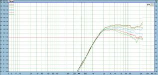
...and a cutout of the respective measurement of the elliptical WG from 1kHz to >20kHz:

Despite the fact that the measurement was done in a baffle and the simulation in an infinite baffle (have to check the measurement and simulation distances as well), I can see some principal similarities:
- Widening of radiation around 13 kHz (0°-30°)
- SPL increase at very high frequencies (>18kHz)
- Dip of SPL moving from 18kHz to around 15kHz under higher angles
I think >10kHz membrane area, geometry and coupling to the WG throat ('gap') has a significant impact. There may be a positive impact of a 'phase shield' and a 'crease' - or diffraction slot as shown below. Next steps, let's see... And the impact of an enclosure of course.
@Andy 19191
Quantification of the possible error induced by coupling of the internal BEM solution to the external BEM solution as performed by ABEC is far beyond my mathematical skills. I have to rely on ABEC here...I didn't know what you had done which is why I asked what boundary condition was being imposed on the flat boundary at the mouth. The answer is that you are coupling the internal BEM solution to an external BEM solution which is better than I suspected but the coupling is still forcing an approximation in the modelling. That is, if you could perform a single external BEM solution along the lines mentioned in the previous post it would be different and closer to what you wish to simulate. However, there is a some chance this difference is not large and that the current computation uses less memory and computing time compared to a full single domain simulation.
If I was performing the simulation, I would want to quantify the size of this approximation and to know how it shows up in the solution.
Thanks a lot for the link, very interesting. And good luck with your old house - sounds like a lot of work to me.Performing simulations of waveguides has been on my hobby to-do list for many years. I made a start about 7 years ago but life outside hobby time stepped in and diverted me elsewhere. I am interested but in 3 weeks I am moving to an old house that needs a great deal of work. I suspect chatting on forums will be the limit of my involvement with speaker DIY for the rest of the year.
Based on the differences induced by either simulating with a membrane exactly matching to the WG throat vs a smaller membrane with a 'gap' between membrane and WG throat (i.e. small part of the HT driver surface) I again checked the SB26ADC membrane geometry and how this is coupled to the WG (please refer to the image give by Augerpro below):
The respective 'model' of the SB26 coupled to the elliptical WG VarC:
Simulation of the horizontal radiation normalized to 0° compared to the simulation of a membrane exactly matching to the WG throat, without gap:
Not really surprising that the coupling of the HT-driver to the WG throat is critical and has a significant impact on radiation at >10kHz.
The corresponding simulation of SPL from 0° to 60°, horizontal radiation:
...and a cutout of the respective measurement of the elliptical WG from 1kHz to >20kHz:
Despite the fact that the measurement was done in a baffle and the simulation in an infinite baffle (have to check the measurement and simulation distances as well), I can see some principal similarities:
- Widening of radiation around 13 kHz (0°-30°)
- SPL increase at very high frequencies (>18kHz)
- Dip of SPL moving from 18kHz to around 15kHz under higher angles
I think >10kHz membrane area, geometry and coupling to the WG throat ('gap') has a significant impact. There may be a positive impact of a 'phase shield' and a 'crease' - or diffraction slot as shown below. Next steps, let's see... And the impact of an enclosure of course.
- Home
- Loudspeakers
- Multi-Way
- Open source Waveguides for CNC & 3D printing!