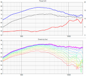
I don't find Troels' 6600 measurement terribly different than yours except >15khz which probably has to do with the different throat - see his adaptor that starts the flare. I also think there is a long way to go using those Scans (except the XT25) in that waveguide, with 6-9dB dips @ 12khz. I think we could do better than that.
Hi,
It's about the adaption of the membrane geometry of the tweeter and the WG throat. This is kind of arbitrary if you combine 'a' WG and 'a' tweeter by chance.
The Jantzen WG has been developed for the AUDAX TW034, a tweeter with relatively large diameter. I think the suggested tweeters in the Monkey Box thread have larger diameters as well (as you are aiming for high SPL and low crossover frequency).
In order to keep (negative) interaction of tweeter and WG-(throat) low and still help with directivity at crossover, I suggested a shallow WG for the project...
However, from my point of view, best solution would be to develop a WG with augerpro as soon as you agreed on a specific tweeter.
Is it possible that the shallow Jantzen waveguide is more 'forgiving' than the deeper WG300?
It's about the adaption of the membrane geometry of the tweeter and the WG throat. This is kind of arbitrary if you combine 'a' WG and 'a' tweeter by chance.
The Jantzen WG has been developed for the AUDAX TW034, a tweeter with relatively large diameter. I think the suggested tweeters in the Monkey Box thread have larger diameters as well (as you are aiming for high SPL and low crossover frequency).
In order to keep (negative) interaction of tweeter and WG-(throat) low and still help with directivity at crossover, I suggested a shallow WG for the project...
Use it with no or a very shallow waveguide in order not to interact with it's very good HF directivity. The WG should 'just' adjust directivity at crossover.
However, from my point of view, best solution would be to develop a WG with augerpro as soon as you agreed on a specific tweeter.
Yes, I was referring to what's happening >15 kHz. The gist was that the peaks and dips I observed were due to the diameter of the dome+surround. However, Troels' measurements do not show these issues, so I wondered if the different depths of the different waveguides might explain the different results. I am just trying to understand what's going on.I don't find Troels' 6600 measurement terribly different than yours except >15khz which probably has to do with the different throat - see his adaptor that starts the flare. I also think there is a long way to go using those Scans (except the XT25) in that waveguide, with 6-9dB dips @ 12khz. I think we could do better than that.
And yes, a custom design for the specific tweeter will be the best solution.
He certainly has peaks/dips in his measurement too, quite close to yours really when you consider how the graphs are scaled. Above 15khz I would make an educated guess that it mostly has to do with differing throats, but yeah, depth can be a reason too. The overall flare looks similar between the two waveguides, so throat and depth would be likely causes, I just come down (perhaps wrongly) that it is the throat more than depth that explains the difference in this particular example.
Do you have a Scan RR on hand?
Do you have a Scan RR on hand?
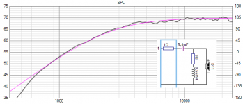
I would expect at least ~93dB/2.83V/1m at 10kHz. Sensitivity usually does not change much above 10kHz with/without WG.
Update: I have to correct #186, I had wrong impedance file = > it is needed standard 2.order crossover configuration to achieve LR2 slope.
Update: I have to correct #186, I had wrong impedance file = > it is needed standard 2.order crossover configuration to achieve LR2 slope.
Attachments
Last edited:
Just a little heads-up: a user here was looking to print one of my designs which prompted me to look at prices again at 3dhubs.com. Prices have really dropped A LOT! 2 years ago these priced around $150-200 a piece! Now you can do PLA @ 100um for $29 or better yet, PETG @ 100um for $36! My favorite, SLS Nylon, is still up there at $93, but that is less than half of what it was 1-2 years ago. I think the economics are definitely shifting away from CNC and to 3D printing.
I would expect at least ~93dB/2.83V/1m at 10kHz. Sensitivity usually does not change much above 10kHz with/without WG.
Update: I have to correct #186, I had wrong impedance file = > it is needed standard 2.order crossover configuration to achieve LR2 slope.
Yep.
That's one of the reasons I'm using a ribbon in my current project. I need to get the efficiency up.
A horn or waveguide can raise the output level below 10khz, but above that, output is basically dictated by the motor and the mass. Ribbons have low mass and big motors.
Just connect the two curves with a spline and your good to go. Celestion uses a negative exit angle on the CDX1-1425 and it works fine. I believe you measured it on the QSC waveguide didn't you? If not, I have both, I can post some measurements. That waveguide was specifically designed for the Celestion CD.
BMS has the widest exit angles I've seen.
BMS has the widest exit angles I've seen.
Brandon, this is a brilliant thread. Has anyone printed anything yet for the SB19? Although the SB21 has the s.r. and a lower fs, I like the narrow diaphragm lip of the SB19. Someone has already said this, but i think this is the SB19, and I have a pair of those woofers: Products — Buchardt Audio
Cheers,
Greg
Cheers,
Greg
Yep.
A horn or waveguide can raise the output level below 10khz, but above that, output is basically dictated by the motor and the mass. Ribbons have low mass and big motors.
As do AMT's.
")
I wish I could have some waveguides printed for my AMT's as they show a lot of promise as well.
Before-and-after with a custom waveguide on the Hygeia RT-50021 AMT
Brandon, I see took-path files for 5", but could you scale the sb21 for 17cm woofer?
I'll be happy to do GB if people want this.
Cheers,
Greg
I'll be doing some larger sizes for the SB21. But you need to define what you mean by "for a 17cm woofer". Acoustic center is deeper, so going a bit deeper makes sense. Other than that everything else is driven by crossover point.
I'll be doing some larger sizes for the SB21. But you need to define what you mean by "for a 17cm woofer". Acoustic center is deeper, so going a bit deeper makes sense. Other than that everything else is driven by crossover point.
Brandon,
Right. That was a quick post before work.
I've never done an alignment with a WG before, therefore, I'm just making some assumptions.
1. The mouth should approximately match the woofer, doesn't have to but would potentially increase linearity in off-axis in and around the x-over range.
2. Motors get nearly aligned, so less slope adjustment for tweeter, so yes, the throat needs to be deeper then with a 5" woofer.
Attached is the driver I will be using: A phenomenal driver that is very easy to work with.
View attachment 6in SB17NAC35-4 REV-3.pdf
3. Target x-over would be at 2k.
I will be happy to order you a pair once you've got a tool-path file.
Cheers,
Greg
Instead of just matching width of drivers, I would match the directivity at the XO point. At the beginning of the thread I defined this match as being -2.5dB (or so) down, 0 to 60 degrees. That woofer has it's -2.5dB @ 1.8-2.0 khz. So ideally the waveguide would also have its -2.5dB at the same point. This is probably a 6" or even a bit bigger guide.
BUT, i think in practice things are a bit looser. For example Revel uses that exact woofer in a small monitor and *I think* the crossover is @2.3khz, but the waveguide is closer to 5" wide. So maybe when the differences are small the drivers blending will still have very smooth power response. Keep in mind if you go with a bigger waveguide you push apart the center-to-center, so their is a compromise here.
Another consideration regarding depth, the apparent acoustic center will change with a HP or LP in place also, but I haven't measured yet exactly how that might affect things. So I'm still not sure what exact depth is a match for any given woofer.
- Home
- Loudspeakers
- Multi-Way
- Open source Waveguides for CNC & 3D printing!