^^Thanks Tony,
The filter I was trying was one built via 3rd part measurements and splice/merging tools (ie. virtual design). The filter in post #20 is the start of xover design based on actual measurements since just recently acquiring a Umik1 mic. My goal was to see if the virtual design was just a little off or way out to lunch. It does not appear to be very accurate from just placing xover values in Xsim using my own raw measurents. But, you are probably right, maybe 2 raw measurements where overlayed. I'll take your advice and just put a coil in series with the woofer and see what roll off effects I observe. I appreciate your assistance!
Best Regards,
Rich
The filter I was trying was one built via 3rd part measurements and splice/merging tools (ie. virtual design). The filter in post #20 is the start of xover design based on actual measurements since just recently acquiring a Umik1 mic. My goal was to see if the virtual design was just a little off or way out to lunch.
It does not appear to be very accurate from just placing xover values in Xsim using my own raw measurents. But, you are probably right, maybe 2 raw measurements where overlayed. I'll take your advice and just put a coil in series with the woofer and see what roll off effects I observe. I appreciate your assistance!Best Regards,
Rich
^^^Hi Ralf,
I'm fairly sure the small blips are from my work station setup up behind mic stand. The usb cable supplied with Umik1 mic needs to be much longer so I can setup computer and amp a further distance away. I'm going to order a 25ft. usb cable today. The good thing is no parts have been ordered; this has been more of an exercise to learn the proper techniques.
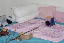
Once I receive everything and get setup; I will take a couple photos of my work area to evaluate. I have only seen a few other setups from posts on this forum so not sure how others overcome their work station potentially effecting measurement accuracy.
Your thoughts and advice are much appreciated!
Best Regards,
Rich
I'm fairly sure the small blips are from my work station setup up behind mic stand. The usb cable supplied with Umik1 mic needs to be much longer so I can setup computer and amp a further distance away. I'm going to order a 25ft. usb cable today. The good thing is no parts have been ordered; this has been more of an exercise to learn the proper techniques.
Once I receive everything and get setup; I will take a couple photos of my work area to evaluate. I have only seen a few other setups from posts on this forum so not sure how others overcome their work station potentially effecting measurement accuracy.
Your thoughts and advice are much appreciated!
Best Regards,
Rich
See post #13
Can I assume there is no setting explicitly called "gate"? Maybe someone can point to a much simpler explanation of setting "the gate". I am not being sarcastic, just trying to figure out how to do this with as little confusion as possible.
If you are measuring inside then I would suggest trying to move as much furniture out of the way as possible. Set up with the Mic and speaker as close to the centre of the room as possible with the speaker positioned so that it is at an oblique angle (not 90 or 45deg) to either side wall.
Try and get the speaker roughly equal in distance from floor and ceiling (unless your floor is very absorbant in which case it may be better with a bigger gap to the ceiling. (your first reflection is likely to be floor, ceiling or both in a typical room with a lowish ceiling.
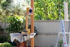
Attached are some old pictures of me measuring a speaker outside. Note that the column behind the speaker is not great but there was limited options. The gating shown was an attempt to get lower frequency at the expense of some hairyness in the higher frequencies.
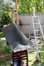
The last two images show a very different measurement setup I did as an expermiment. It seemed to work reasonably well as a sort of nearfield ground plane type measurement.
Tony.
Try and get the speaker roughly equal in distance from floor and ceiling (unless your floor is very absorbant in which case it may be better with a bigger gap to the ceiling. (your first reflection is likely to be floor, ceiling or both in a typical room with a lowish ceiling.
Attached are some old pictures of me measuring a speaker outside. Note that the column behind the speaker is not great but there was limited options. The gating shown was an attempt to get lower frequency at the expense of some hairyness in the higher frequencies.
The last two images show a very different measurement setup I did as an expermiment. It seemed to work reasonably well as a sort of nearfield ground plane type measurement.
Tony.
Attachments
^^^Thanks Tony,
That helps a lot seeing how those with much experience do things. I see where my setup could be improved a bit for better results. The next speakers to test will be a challenge getting higher off the ground then a few feet since they weigh approximately 125 pounds each.
Best Regards,
Rich
That helps a lot seeing how those with much experience do things. I see where my setup could be improved a bit for better results. The next speakers to test will be a challenge getting higher off the ground then a few feet since they weigh approximately 125 pounds each.
Best Regards,
Rich
Attachments
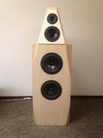
Yes! when I was doing the measurements for my 10" woofers I couldn't use the stand (70L cabinets) My MTM's are about the limit for that stand.
I put the woofers on the edge of a table and the MTM's on top and moved it right to the edge of the deck.
Nice speakers BTW!
Tony.
when I was doing the measurements for my 10" woofers I couldn't use the stand (70L cabinets) My MTM's are about the limit for that stand. I put the woofers on the edge of a table and the MTM's on top and moved it right to the edge of the deck.
Nice speakers BTW!
Tony.
Thanks Tony,
I appreciate the compliment. My situation is a little unique in that I live and work at a Golf course that is closed during winter months due to snow cover. The Golf course has a Clubhouse with a rather large dining area that is now my speaker measuring laboratory(at least until the course opens in April). Your assistance has been valuable in giving me some ideas on how to set things up moving forward. I have three pairs of DIY speakers to measure and assemble xovers for before April 1(two 2ways and one 3way). May not get it all done but there is always next winter to resume the projects. Probably will learn something else hanging out on this forum that will cause me to re-visit my work anyway.
Best Regards,
Rich
I appreciate the compliment.
My situation is a little unique in that I live and work at a Golf course that is closed during winter months due to snow cover. The Golf course has a Clubhouse with a rather large dining area that is now my speaker measuring laboratory(at least until the course opens in April). Your assistance has been valuable in giving me some ideas on how to set things up moving forward. I have three pairs of DIY speakers to measure and assemble xovers for before April 1(two 2ways and one 3way). May not get it all done but there is always next winter to resume the projects. Probably will learn something else hanging out on this forum that will cause me to re-visit my work anyway.Best Regards,
Rich
Hi Rich,
I just got the chance to read through the thread. Nice work so far.
A few comments:
Your offset technique works and it never hurts to double check your results in a secondary program (ie. PCD), but you can do the same offset procedure using single driver and combined driver measurements in XSim as well. In other words, no need to do it 1st in PCD.
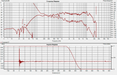
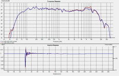
In post 20, you've shown 3 measurements which look like the woofer, tweeter and woofer and tweeter combined, all farfield. Did you also take a nearfield of the woofer? And then blend near and far field of the woofer together? Smoothly? And if you wanted to, you could take the port nearfield as well.
Baffle step, baffle step, baffle step.......... Try this for a 2-way placed out in a room decently far from walls: include the full 6dB loss in your xo sims, play the speakers properly positioned in your room with the xo as designed and then decide - too much bass? Alter your sims and xo accordingly.
At this point now, the biggest question for me is what are you using for your impedance files? Have you made up a little Limp jig and actually taken impedance measurements of the drivers in the box with REW (well, in a 2-way, it really only matters that the woofer is in the box), because that is what you should do for the sake of simulation accuracy. Info is in REW's help files under Impedance and/or Google limp jig images. It's actually pretty simple.
Since no matter where you place your 3-ways, the woofers will always be the same distance from the floor, I would suggest you will want to include the floor effects in your woofer measurements. You are going to want to see what those effects are and see whether or not you can mitigate them to some extent in any of your xo choices.
Also, in XSim, turn off the system phase response - it doesn't really serve any purpose does it? Maybe try to align the driver phases a little better in the xo region and your tweeter is perhaps looking a little hot above about 8kHz
Cheers
I just got the chance to read through the thread. Nice work so far.
A few comments:
Your offset technique works and it never hurts to double check your results in a secondary program (ie. PCD), but you can do the same offset procedure using single driver and combined driver measurements in XSim as well. In other words, no need to do it 1st in PCD.
In post 20, you've shown 3 measurements which look like the woofer, tweeter and woofer and tweeter combined, all farfield. Did you also take a nearfield of the woofer? And then blend near and far field of the woofer together? Smoothly? And if you wanted to, you could take the port nearfield as well.
Baffle step, baffle step, baffle step.......... Try this for a 2-way placed out in a room decently far from walls: include the full 6dB loss in your xo sims, play the speakers properly positioned in your room with the xo as designed and then decide - too much bass? Alter your sims and xo accordingly.
At this point now, the biggest question for me is what are you using for your impedance files? Have you made up a little Limp jig and actually taken impedance measurements of the drivers in the box with REW (well, in a 2-way, it really only matters that the woofer is in the box), because that is what you should do for the sake of simulation accuracy. Info is in REW's help files under Impedance and/or Google limp jig images. It's actually pretty simple.
Since no matter where you place your 3-ways, the woofers will always be the same distance from the floor, I would suggest you will want to include the floor effects in your woofer measurements. You are going to want to see what those effects are and see whether or not you can mitigate them to some extent in any of your xo choices.
Also, in XSim, turn off the system phase response - it doesn't really serve any purpose does it? Maybe try to align the driver phases a little better in the xo region and your tweeter is perhaps looking a little hot above about 8kHz
Cheers
Hi jReave,
It is so great to hear from you! I have aso been capturing nearfield of woofer and port in the measurement process. From there I have followed Bagby's approach and spliced them together in PCD7. And from there, blend farfield with summed response of woofer/port nearfield using Frequency Response Blender. In a word, I have followed Jeff Bagby's white papers that you had pointed me to some time back.
As for impedance measurements, I did put together a limp jig and it is working out well. Your thoughts on dealing with baffle step makes perfect sense.
A few questions: (if you don't mind)
1. On individual drivers measured in REW do I need to deal with minimum phase or can I just extract it later using either Frequency Response Blender or Response Modeler? My current method has just been to unwrap phase before exporting. And of course extract minimum phase if splicing nearfield with farfield in Frequency Response Blender.
2. How do I insure impulse response accuracy in REW (in regards to time alignment) between sequential driver measurements? I see a loopback technique used but it does not apply when usb mic is used so that rules out my Umik1 mic. Also there is mentioned in the REW help docs a timing reference method but that seems to be more for setting up multi speakers in a room. It says "If a timing reference is not used REW will se IR zero time according to the setting of SET t=0 at IR peak" Am I worrying over nothing?
3. How does one go about dialing in acoustic offsets using Bagby's method when dealing with 3 ways? His white paper uses a two way for the example. In my case, I will measuring a 3 way with dual woofers ie. TMWW configuration. Would I just splice farfield of both woofers driven together with farfield of mid/tweeter farfield in Frequency Response Blender then use either Xsim or PCD7 to dial in relative acoustic offsets?
4. Along those lines, do I use 1 woofer in PCD7 for Xover design? Even though I'm dealing with a dual woofer 3 way. There does not seem to be an accurate way to measure each woofer individually in the speaker box. Since there is the ability to input both woofers coordinates in PCD7; that would appear to be the most accurate method but may not be possible.
Sorry for such a long post. Hopefully, my rambling on made some sense. As always, your thoughts and direction are much appreciated!
Best Regards,
Rich
It is so great to hear from you!
I have aso been capturing nearfield of woofer and port in the measurement process. From there I have followed Bagby's approach and spliced them together in PCD7. And from there, blend farfield with summed response of woofer/port nearfield using Frequency Response Blender. In a word, I have followed Jeff Bagby's white papers that you had pointed me to some time back.As for impedance measurements, I did put together a limp jig and it is working out well. Your thoughts on dealing with baffle step makes perfect sense.
A few questions: (if you don't mind)
1. On individual drivers measured in REW do I need to deal with minimum phase or can I just extract it later using either Frequency Response Blender or Response Modeler? My current method has just been to unwrap phase before exporting. And of course extract minimum phase if splicing nearfield with farfield in Frequency Response Blender.
2. How do I insure impulse response accuracy in REW (in regards to time alignment) between sequential driver measurements? I see a loopback technique used but it does not apply when usb mic is used so that rules out my Umik1 mic. Also there is mentioned in the REW help docs a timing reference method but that seems to be more for setting up multi speakers in a room. It says "If a timing reference is not used REW will se IR zero time according to the setting of SET t=0 at IR peak" Am I worrying over nothing?
3. How does one go about dialing in acoustic offsets using Bagby's method when dealing with 3 ways? His white paper uses a two way for the example. In my case, I will measuring a 3 way with dual woofers ie. TMWW configuration. Would I just splice farfield of both woofers driven together with farfield of mid/tweeter farfield in Frequency Response Blender then use either Xsim or PCD7 to dial in relative acoustic offsets?
4. Along those lines, do I use 1 woofer in PCD7 for Xover design? Even though I'm dealing with a dual woofer 3 way. There does not seem to be an accurate way to measure each woofer individually in the speaker box. Since there is the ability to input both woofers coordinates in PCD7; that would appear to be the most accurate method but may not be possible.
Sorry for such a long post.
Hopefully, my rambling on made some sense. As always, your thoughts and direction are much appreciated!Best Regards,
Rich
I have also been capturing nearfield of woofer and port in the measurement process. From there I have followed Bagby's approach and spliced them together in PCD7. And from there, blend farfield with summed response of woofer/port nearfield using Frequency Response Blender. In a word, I have followed Jeff Bagby's white papers that you had pointed me to some time back.
As for impedance measurements, I did put together a limp jig and it is working out well.
Excellent. That sounds good.
To answer your questions:
1. I think that when you combine nearfield with farfield measurements, you need to extract minimum phase afterward. Not 100% sure on that one but that's what I do. I therefore ignore phase on all driver measurements and extract minimum phase for all of them afterwards.
2. I may be wrong on this but I think you are worrying here about nothing concerning impulse response timing. I think the FR measurements are fine with the way you have the IR currently setup in REW.
3 & 4. When 2 drivers are used in the same chamber, you really don't have much choice but to measure them together in the farfield. Nearfield though you can only measure 1 driver at a time.
So measurements for your 3-way should go like this (with mic set on the tweeter axis probably a minimum distance of about 30"):
- measure tweeter
- measure mid
- measure the 2 woofers together
- measure the tweeter and mid together
- measure the tweeter and woofers together
- (optional - measure the mid and woofers together and you can double check your woofer offset which will be an average between the 2 woofers' individual offsets)
- measure the mid nearfield
- measure each woofer nearfield to ensure they are both the same but you'll only need to use 1 of them afterward
- measure the port nearfield
- measure impedance of the tweeter, mid and the 2 woofers together
For mid offset, do the tweeter and mid like in a 2-way. Then do the same thing with the tweeter and double woofer measurement for the woofer offset and you can double check that by doing the mid and woofers together too.
Then you'll blend the near and farfield for the mid and blend the port and woofer nearfield (single) and farfield (double). This latter will be the response for the 2 woofers together so although it's 2 drivers, in PCD or XSim, you'll set it up as just a single one. Notice that impedance will be for the 2 together as well and the single offset for the woofers should be at a point pretty close to right in between them.
Hope that helps.
On point 2. if you are extracting minimum phase and putting in the offsets in the simulation then yes it is not something you need to worry about.
It is only important if you want the relative offsets of the drivers imbedded in the measurements (which won't work if you are splicing nearfield and farfield). When you have the relative offsets in the measurements you can model in the crossover simulation without putting in any driver offsets, as the offsets are already in the measurements
I've traditionally used speaker workshop which only allows Z offset to be input (and I didn't know how to measure the z offset until I read Charlies paper on it, relatively recently) so I had to rely on imbedded offsets in the measurements. They are good for sanity checking as well.
Tony.
- Status
- This old topic is closed. If you want to reopen this topic, contact a moderator using the "Report Post" button.
- Home
- Loudspeakers
- Multi-Way
- Need help interpreting measurements