I just looked up the JBL, and see it is a three way. I assumed it was just a tweeter with intergrated cap... that makes more sense now. Sorry I was not understanding the situation fully.
Tony.
Hi, not an issue, my bad for not sharing all the details. So I understand correct, that padding this whole thing would be risky? I don't mind decreasing JBL woofers DB, since I have another standalone woofer, but I'm just worried about the resistor being overwhelmed. I can get 6.8 Ohm 100 W LPAD. This should be capable of handling the power? Maybe mount it on heatsink?
If you want to separate the JBL and the woofer completely, then you'll have to put a HPF on the JBL.
5.6 ohm + 2 ohm = 7.6 ohm. I think I remember that the woofer is 12 ohm, so ~8 ohm || 12 ohm is about 4.5 ohm, which your amp will be fine with.
I don't know how the integrated XO would react to additional HPF but this sounds like an option. I don't mind, if JBLs woofer would be shut off and JBL as whole, used only for mids and highs.
I think probably the best thing to do is just try the 5.6 ohm as Mrcloc has suggested, and see how it goes. You may find that the bass from the sub is too weak, but on the other hand the JBL will be running full range so should (provided there aren't big phase differences) augment the bass coming from the sub.
Tony.
Tony.
What is the value of the coil you wound? I'm putting some stuff in the simulator to get a rough idea of how this will work, but need to know the coil value")
Tony.
Value is 0.793mH rounded up to 8mH.
Ok So this sim is far from reality but it does show that you will likely still be reaching for the bass control (to turn it down!)
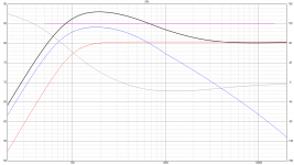
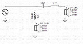
What I did was I simmed the woofer in the 10L sealed cabinet and exported the frequency response and impedance from that sim.
Then I created a curve for the jbl which is basically flat with a 2nd order butterworth roll-off at 100Hz. I used a completely flat 2 ohms impedance for the JBL which will not be realistic.
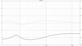
The fact the JBL is running full range means you get a BIG boost in the bass region, also because the JBL is only a two ohm driver the 5.6 series resistance drops it's sensitivity a lot. The overall impedance seems to be ok (but marginal).
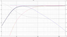
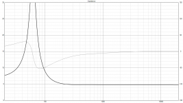
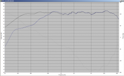
The addition of a 68uF cap in series with the JBL allows dropping the 5.6 ohm resistor to 2.7 ohms, giving a much better result for both spl and impedance. I'm not sure however how this would interact with the existing crossover in the jbl, so I tried putting a 68uF cap in front of the crossover for my MTM that I have in vituixcad, and it pretty much just rolled off the bottom end leaving the rest of the response intact , So I think it would be worth getting a 68uF bipolar electrolytic to try it out. They can be had cheap enough 68uF 100V Electrolytic Non-Polarized Crossover Capacitor
Images of the sims attached. Last image compares my normal MTM response sim (black) to with a 68uF cap added in before the other crossover components (blue).
Tony.
What I did was I simmed the woofer in the 10L sealed cabinet and exported the frequency response and impedance from that sim.
Then I created a curve for the jbl which is basically flat with a 2nd order butterworth roll-off at 100Hz. I used a completely flat 2 ohms impedance for the JBL which will not be realistic.
The fact the JBL is running full range means you get a BIG boost in the bass region, also because the JBL is only a two ohm driver the 5.6 series resistance drops it's sensitivity a lot. The overall impedance seems to be ok (but marginal).
The addition of a 68uF cap in series with the JBL allows dropping the 5.6 ohm resistor to 2.7 ohms, giving a much better result for both spl and impedance. I'm not sure however how this would interact with the existing crossover in the jbl, so I tried putting a 68uF cap in front of the crossover for my MTM that I have in vituixcad, and it pretty much just rolled off the bottom end leaving the rest of the response intact , So I think it would be worth getting a 68uF bipolar electrolytic to try it out. They can be had cheap enough 68uF 100V Electrolytic Non-Polarized Crossover Capacitor
Images of the sims attached. Last image compares my normal MTM response sim (black) to with a 68uF cap added in before the other crossover components (blue).
Tony.
Attachments
Last edited:
- Status
- This old topic is closed. If you want to reopen this topic, contact a moderator using the "Report Post" button.
- Home
- Loudspeakers
- Multi-Way
- Mid and high range speakers