we are talking about baffle edge diffraction which refers to a specific phenomenon where the sound wave creates an out of phase reflection due to the impedance change.
Understanding Cabinet Diffraction – Audioblog
i'd like clarification of this statement if i may, when you say impedance change are you saying the driver impedance is changing and if so how?
the linked article makes no mention of impedance variations either (just trying to understand)
Actually, it is surprising how important way-off axis response is! One must think about the listening situation in an acoustically small room. In Europe and Asia most living rooms are actually quite small (3x5m average?) an built from concrete elements, which is worst scenario. Same goes to most rooms I have seen at diyaudio.com.
Directivity (index and change of that index per frequency) has been one of major design and evaluation criteria for last 20-30 years, based on work of Toole, Geddes etc. There is no generally accepted criteria for distribution and weighting of hor and vert angles, or number of DI. Loudspeaker companies that (mostly) follow these guidelines are JBL, Genelec, Amphion, KEF, Elac etc.
Here is a nice collection of wide angle dispersion measurements 3D3A Lab at Princeton University
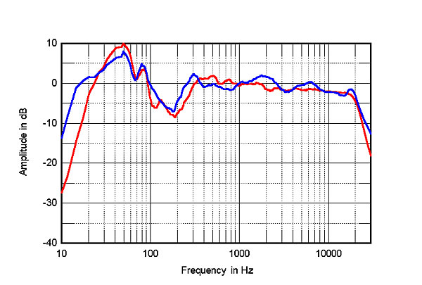
Stereophile magazine has done measurements of loudspeakers for decades, off-axis for more than 20 years. Some of their reports have also in-room measurements, and it is very interesting to compare lab and room measurements vs. listening impressions - some astonishing reports included! Sonus Faber Aida beats Wilson's top model in smoothness! Red line in graph. B&W top models are strange fruits - in-room is much better than near-axis would indicate.
Directivity (index and change of that index per frequency) has been one of major design and evaluation criteria for last 20-30 years, based on work of Toole, Geddes etc. There is no generally accepted criteria for distribution and weighting of hor and vert angles, or number of DI. Loudspeaker companies that (mostly) follow these guidelines are JBL, Genelec, Amphion, KEF, Elac etc.
Here is a nice collection of wide angle dispersion measurements 3D3A Lab at Princeton University
Stereophile magazine has done measurements of loudspeakers for decades, off-axis for more than 20 years. Some of their reports have also in-room measurements, and it is very interesting to compare lab and room measurements vs. listening impressions - some astonishing reports included! Sonus Faber Aida beats Wilson's top model in smoothness! Red line in graph. B&W top models are strange fruits - in-room is much better than near-axis would indicate.
Last edited:
Where, in this context, there was a baffle normal to the pressure wave, the pressure now causes velocity in the new direction down beside the cabinet, and dissipates to some degree. In the bigger picture this could be termed an (acoustic) impedance change, and these can be responsible for reflections.i'd like clarification of this statement if i may, when you say impedance change are you saying the driver impedance is changing and if so how?
thanks Allen i'm not sure i understand the whole velocity new direction thing.
i understand it as the same frequency radiated by two sources separated by a distance, over time hence comb filtering or that new age term "diffraction"
is it true that sharp angles(as opposed to rounded surfaces)increase diffraction?
i understand it as the same frequency radiated by two sources separated by a distance, over time hence comb filtering or that new age term "diffraction"
is it true that sharp angles(as opposed to rounded surfaces)increase diffraction?
In more general terms, radiating into half space (baffle) and into full space (around the box) represent a different acoustic impedance. (The same power may exist in the second instance for eg, with -3dB in front and the same behind the imaginary baffle plane, also with a drop in pressure of 6dB comparing on axis.)
I mentioned direction not only because I was following the changing events, but also to allude that sometimes there may be more to the end result.. even though it is sometimes still simply called an impedance change when the context dictates. Other times though, a large wave through a smaller duct that changes its size will see the impedance change and it results in a reflection that is simple, ie one mode along the original line of travel. This might also just be referred to as a resonance if it suits the context.
It really makes sense to consider these more specific aspects separately.
Think of it this way. The fallout from the change will appear to be a redirection of energy that follows a pattern that indicates the location of the disruption, as its source.
I don't think I'd describe it that way because in a sense, the same amount of changing is still occurring. A roundover can spread diffraction in time, and in space. As I suggested above in parentheses, that broadly speaking if you can spread power around you decrease the directivity index and the apparent relative pressure level, but there are other reasons rounding helps.is it true that sharp angles(as opposed to rounded surfaces)increase diffraction?
Thinking of (sound)waves makes it too difficult to understand diffraction. Actually it is a pulsating and propagating change in pressure of air, which is described graphically as wave (y-axis is pressure, X is time)
ACOUSTICAL FUNDAMENTALS | Pro Audio Encyclopedia
ACOUSTICAL FUNDAMENTALS | Pro Audio Encyclopedia
Practical approach to diffraction control
Dear all,
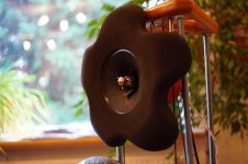
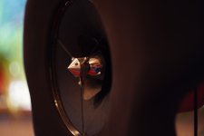
my latest attempt to control diffraction and dipole effects (which I just for myself classify as geometrical resonances) is a petal-shaped baffle with large differences in the return path and large, variable radii at any edges. This geometry rewarded me with a clearer and more relaxed representation than every prototype before, with better imaging, same driver and crossover.
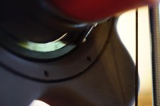
The only issue I´m not happy with is the small step between cone and baffle, but this is due to driver construction and can´t be avoided.
Some will argue that a spherical baffle is a bad approach, and in theory of course that´s right. With the petals however, I haven´t found any negative effects so far (sorry, no measurements yet, I´m not at home in the moment...), but found that I preferred the spherical baffle to rectangular and trapezoid shapes.
Some will argue that all this is meaningless in a dipole, due to the dipole null, but after several prototypes I´m of the opinion that diffraction control matters in dipoles as well.
All the best
Mattes
Dear all,
my latest attempt to control diffraction and dipole effects (which I just for myself classify as geometrical resonances) is a petal-shaped baffle with large differences in the return path and large, variable radii at any edges. This geometry rewarded me with a clearer and more relaxed representation than every prototype before, with better imaging, same driver and crossover.
The only issue I´m not happy with is the small step between cone and baffle, but this is due to driver construction and can´t be avoided.
Some will argue that a spherical baffle is a bad approach, and in theory of course that´s right. With the petals however, I haven´t found any negative effects so far (sorry, no measurements yet, I´m not at home in the moment...), but found that I preferred the spherical baffle to rectangular and trapezoid shapes.
Some will argue that all this is meaningless in a dipole, due to the dipole null, but after several prototypes I´m of the opinion that diffraction control matters in dipoles as well.
All the best
Mattes
Attachments
Some will argue that all this is meaningless in a dipole, due to the dipole null, but after several prototypes I´m of the opinion that diffraction control matters in dipoles as well.
Do you care to support that opinion with some measurements?
B.
Some will argue that a spherical baffle is a bad approach, and in theory of course that´s right. With the petals however, I haven´t found any negative effects so far (sorry, no measurements yet, I´m not at home in the moment...), but found that I preferred the spherical baffle to rectangular and trapezoid shapes.
Some will argue that all this is meaningless in a dipole, due to the dipole null, but after several prototypes I´m of the opinion that diffraction control matters in dipoles as well.
All the best
Mattes
The "petals" baffle that you have constructed should (I think) have worse diffraction than a planar baffle of whatever shape. In a dipole system, where the front and rear waves meet there is strong cancellation. This is often at the baffle edge, the same place that the "cabinet edge" type of diffraction would occur. So for a dipole system with a planar baffle, most of the edge diffraction is eliminated as long as the edge is being illuminated by both front and rear waves (e.g. not if the driver is beaming strongly).
In your petal setup, there are edges that occur before the baffle edge. These come from the folding of the baffle into the petal shape. This happens on both the front and rear. So my guess is that this will have some "edge diffraction" more so than a planar baffle. Also, you are expanding space in front of the driver but at the same time constricting space behind the driver with the petals. This may also be influencing what is going on with the response.
Although it is certainly good that you feel it sounds better, the mind and perception can be very tricky. It would be great to have measurements on several angle to normal and a comparison to a square planar baffle of about the same dimensions. If that is possible to do and post here, I would very much like to take a look.
In a dipole system, where the front and rear waves meet there is strong cancellation. This is often at the baffle edge, the same place that the "cabinet edge" type of diffraction would occur. So for a dipole system with a planar baffle, most of the edge diffraction is eliminated as long as the edge is being illuminated by both front and rear waves (e.g. not if the driver is beaming strongly).
I fail to see why people believe that this happens like that. To me the huge cancellation at the edge would cause a large reflection and reradiation of same. This IS diffraction. So, to me, dipoles have far more edge diffraction than a closed box. It's just that at LFs this diffraction blends into the direct radiation to create the dipole radiation pattern, but higher up this diffraction is still an issue.
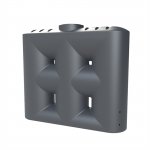
A driver at the center of a donut would have the least possible HF diffraction while still maintaining a LF dipole pattern. Kind of like a dipole waveguide.
A driver at the center of a donut would have the least possible HF diffraction while still maintaining a LF dipole pattern. Kind of like a dipole waveguide.
Some slimline water tanks have (pretty much) this shape.
If I wanted to build such an object, I'd cut and weld together a few used polyethylene food drums. They are cheap, robust, and would lend themselves to making this sort of shape.
These are options I considered for my outdoor (bush block) sound system, but would be pretty overbearing for indoor use!
Attachments
Counterintuitively it can make sense to have an unavoidable gap very close to the source, subject to conditions, and often at lower/middle frequencies.the small step between cone and baffle, but this is due to driver construction and can´t be avoided.
I fail to see why people believe that this happens like that. To me the huge cancellation at the edge would cause a large reflection and reradiation of same. This IS diffraction. So, to me, dipoles have far more edge diffraction than a closed box. It's just that at LFs this diffraction blends into the direct radiation to create the dipole radiation pattern, but higher up this diffraction is still an issue.
A driver at the center of a donut would have the least possible HF diffraction while still maintaining a LF dipole pattern. Kind of like a dipole waveguide.
Doesn't the Quad Esl 63 do something those lines?
Doesn't the Quad Esl 63 do something those lines?
I haven't the slightest idea!! I don't follow dipoles!
I agree - open baffle midrange has much worse diffraction than even a sharp cornered shoe box shape closed box...I fail to see why people believe that this happens like that. To me the huge cancellation at the edge would cause a large reflection and reradiation of same. This IS diffraction. So, to me, dipoles have far more edge diffraction than a closed box. It's just that at LFs this diffraction blends into the direct radiation to create the dipole radiation pattern, but higher up this diffraction is still an issue.
Years ago I was experimenting with foam damping strips on the rear of the cone of a full range driver - which involved a lot of tedious iteration of the positioning of the strips and precise measurements without moving the cabinet.
I was having to unscrew the driver out of the front of the cabinet, make the change to the damping strips on the back of the cone, then screw it back in to the cabinet all while the cabinet remained vertical to avoid disturbing it's exact location relative to the microphone so that I could capture subtle changes that the dampings strips were responsible for.
In an effort to speed up this process, and because I was only focusing on 2-5Khz, I decided to remove the removable front panel and simply clamp it upright to a bracket so I could walk around the back and make changes without removing the driver from the panel at all.
Same size panel, (about 60cm x 40cm) same driver, but now open baffle instead of a shoebox. Big mistake. The ripple in the response in the midrange was massive - several dB of up and down ripple going all the way from the baffle transition frequency at about 300Hz up to nearly 2Khz. Yuck!
It made any evaluation of the tweaks I was trying to make impossible so I went back to the closed box and tediously removing and refitting the driver for each test. It also put me off the idea of open baffle midrange in general given that flatness of frequency response is super critical in the midrange, yet an open baffle will inevitably introduce a lot of ripple into the response from the transition frequency of the baffle up until the driver starts to beam.
An open baffle surely doubles the the amount of diffraction issues because you have a second wave propagating from the rear of the driver along the rear of the panel that then diffracts at the edge as well, in the opposite direction.
If they were perfectly out of phase and equal they might in theory cancel but they can't be perfectly in phase with a cone shaped driver as there is no front/rear symmetry of the driver relative to the plane of the baffle, (especially at higher frequencies) so there will be a complex and ugly interaction at the edge rather than complete cancellation.
Last edited:
Diffraction is a problem that has to be dealt with if you want good results, that much is obvious. Slapping a driver with no directivity control like a standard dome tweeter on a flat baffle shoebox with sharp edges and then tweaking the crossover to try to compensate for the horrible response anomalies the diffraction will cause is not a solution. Nor is offsetting the driver to try to make the on axis response look flatter. (There is still just as much diffraction as before - just "moved around" and smeared a bit differently in time. Sorry asymmetric driver positioning fans...Buchardt Audio says that their deep deep waveguide reduces diffractions by 90% and thus they do not use baffle with a rounded edges.
 )
)There's two main ways to deal with diffraction, or at least high frequency diffraction, which is most damaging kind as it affects imaging, subjective smoothness of the sound, and the smoothness of the polar response of the speaker... Driver directivity, or cabinet/baffle shape. (Curves, rounding of edges etc)
Personally I find using drivers with built in directivity MUCH easier than trying to build some very elaborate curved monstrosity of a cabinet. Typical router bit rounding of the edges of a shoebox cabinet are only marginally effective, and only at high treble frequencies doing little if anything at midrange or low treble frequencies. You have to build something massively curved and pretty unusual looking to have any real effect on diffraction down to high midrange frequencies through cabinet shape alone - something like a KEF blade.
So if you go the cabinet shape route you're either only paying lip service to the problem, (router bit rounding) not really solving it, or building a very elaborate non DIY friendly cabinet. And at the end of all that work you still have a speaker with little directivity control. Some people might like that, I don't.
The directional driver route on the other hand solves a lot of problems at once IMHO. You end up with a speaker with controlled directivity, you can build a much more ordinary shoebox cabinet if you wish (or if it's all you can build) but still achieve very low levels of diffraction, realistically speaking lower than what you could achieve with only cabinet design - a lot lower. (And as an added bonus the additional depth of a waveguide tweeter can be used to solve the problem of acoustic centre offset from the mid driver without a stepped baffle or a time delay in the crossover)
That's the route I took. 8" dual cone full range driver as a midbass driver, then a waveguide loaded ribbon tweeter crossing over at 3Khz. All in a boring shoebox without even roundovers on the edges. (Although next time I would do some roundovers for aesthetics only)
The midbass driver becomes sufficiently directional by about 2Khz to minimise illumination of the baffle edge, (so cabinet edge diffraction is already minimal by 2Khz) while the whizzer cone helps delay the full onset of beaming by another octave (until above about 4Khz) to allow a better match with the waveguide ribbon, taking over from 3Khz. Although there is some measurable diffraction from the cabinet edge it is surprisingly minimal, and frequency response variations a few degrees off the horizontal axis as a result of diffraction are very minimal.
This is not surprising because I have measured (and used) the same ribbon tweeter without any baffle at all before just sitting on the top of a cabinet and while there is some difference in response between baffled and unbaffled at around 10Khz the response is remarkably similar in both cases whereas on a traditional dome the response will be radically different without a baffle. Directly comparing the on axis response of a tweeter on a large flat baffle vs held in mid air in a clamp with no baffle at all is actually a really good test of the inherent directivity control of a tweeter. A traditional flat faceplate dome tweeter will fail the unbaffled measurement test miserably, but any decent waveguide tweeter should give an acceptable response without any baffle that doesn't deviate too significantly from the baffled response.
Of course you can combine driver directivity with a curved cabinet design as well, but after getting such good results purely from driver directivity in a boring but easy to build shoebox I'm not sure whether it's worth it for anything other than aesthetic reasons... I will certainly try to improve the aesthetics of the cabinet in my next design, but for looks rather than diffraction reduction as it will also be using controlled directivity drivers and should have similar low baffle diffraction as a consequence.
Last edited:
Dear all,
please allow some time before I´ll be able to make and post measurements - I´m at work in the moment and far away from home. I will need a few weeks more until I have anything more to share. I´m also afraid that I won´t make a second baffle without roundovers and a third baffle without petals anytime soon, sorry.
For sure my subjective impressions are just this. I have never, like Simon has done, made a direct comparison between CB and OB. But I have had my first OB speaker now nearly 35 years ago (with CORAL BETA 8S, Simon! Sadly sold them long ago...) and have always liked OB, be it with dynamic, planar or ESL drivers. Of course, to each his own.
Allen, could you elaborate on any positive effects a small gap or step might have? No offense, I´m just wondering...
The gap between cone and baffle is only a few tenth of a millimetre, so I´m more worried about the 5 mm step between cone and baffle, although it´s slightly rounded. But the step is inherent in the driver´s construction, there´s no way to change it.
All the best
Mattes
In that context yes, but I like the option of making the primary part of the baffle a significant size to get the wave off to a good start and dispense of most of it before needing to let it go. Like yourself I prefer things not to happen by accident.So if you go the cabinet shape route you're either only paying lip service to the problem, (router bit rounding) not really solving it, or building a very elaborate non DIY friendly cabinet.
- Status
- This old topic is closed. If you want to reopen this topic, contact a moderator using the "Report Post" button.
- Home
- Loudspeakers
- Multi-Way
- Baffle Diffraction