There use to be a magazine called "Audio"
He was the tester of loud speakers for them.
There, you can read about him.
you can also find his work in the JAES.
(I made an error. I meant to say 0.25 inches).
That's a pretty shoddy way to cover your loudly voiced denunciation of Blauert and Laws.
Yes, Heyser was a swell fellow (dead for 30 years). But you still have to back up your words when you say another post was BS.
Do you know the difference between Audio Magazine and the Journal of ACA?
Funny, on this forum, whenever somebody gets caught with their hand in the cookie jar, they answer "look it up yourself".
B.
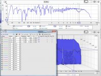
I look for uniformity in the wavelet plots, especially trough the crossover region.
Looking at a pure Dirac pulse in a wavelet would show the ultimate example") .
.
Together with phase plots, FR and waterfall we can see how well the actual summing is. There seem to be no gross errors here, time wise at the crossover, but the reduced SPL at or around the crossover is real. Probably because the drivers themselves showed deviations from ideal curves too. No plot is more important by itself, all are related after all, so I do use them all to form an opinion.
I'd choose frequency (SPL) balance over timing. First thing we hear definitely is frequency balance. I look at timing as a secondary goal, maybe even further down as off axis data still is important for overall tonality.
I don't mind a little drop at 3 kHz, for other reasons not relevant to post here. But the difference in some plots here is close to 6 dB. That might be a bit much.
We still don't know how this asymmetric crossover holds up off axis. That can and will influence the added room energy.
I responded here to highlight some of the tools available. Things to look for. We still haven't covered all of it, like the filtered IR etc. Separate measurements from woofer and tweeter, after making sure they are timed identical in REW, could be filtered to show if they are indeed in phase. I've demonstrated that at one point using a virtually created perfect LR crossover.
I do not save exercises like that, sorry. If you send me the tweeter info, and woofer I could show it I suppose. No idea when I have time for that during the work week.
It could help to get a grip on what tools are available. To get people look beyond the usual FR/IR tabs, with the chance to make the wrong assumptions.
I use all of these tabs, go trough timing sliders etc. to determine my DSP processing.
I draw my own curves in a way, with the help of acoustic room treatment to get the reflections out of my way. That's how I studied to be able to link the different views to what I hear out in the room.
Clean IR's do sound pretty good to me though. Not as boring as a lot of people make it out to be. Especially with some tricks.
Looking at a pure Dirac pulse in a wavelet would show the ultimate example
.Together with phase plots, FR and waterfall we can see how well the actual summing is. There seem to be no gross errors here, time wise at the crossover, but the reduced SPL at or around the crossover is real. Probably because the drivers themselves showed deviations from ideal curves too. No plot is more important by itself, all are related after all, so I do use them all to form an opinion.
I'd choose frequency (SPL) balance over timing. First thing we hear definitely is frequency balance. I look at timing as a secondary goal, maybe even further down as off axis data still is important for overall tonality.
I don't mind a little drop at 3 kHz, for other reasons not relevant to post here. But the difference in some plots here is close to 6 dB. That might be a bit much.
We still don't know how this asymmetric crossover holds up off axis. That can and will influence the added room energy.
I responded here to highlight some of the tools available. Things to look for. We still haven't covered all of it, like the filtered IR etc. Separate measurements from woofer and tweeter, after making sure they are timed identical in REW, could be filtered to show if they are indeed in phase. I've demonstrated that at one point using a virtually created perfect LR crossover.
I do not save exercises like that, sorry. If you send me the tweeter info, and woofer I could show it I suppose. No idea when I have time for that during the work week.
It could help to get a grip on what tools are available. To get people look beyond the usual FR/IR tabs, with the chance to make the wrong assumptions.
I use all of these tabs, go trough timing sliders etc. to determine my DSP processing.
I draw my own curves in a way, with the help of acoustic room treatment to get the reflections out of my way. That's how I studied to be able to link the different views to what I hear out in the room.
Clean IR's do sound pretty good to me though. Not as boring as a lot of people make it out to be. Especially with some tricks.
There seem to be no gross errors here, time wise at the crossover, but the reduced SPL at or around the crossover is real. Probably because the drivers themselves showed deviations from ideal curves too.
In this instance, I was going strictly for Time-alignment. The lost in SPL at the crossover region is a consequence. It would have been nice to have it level with the rest but I have to accept some limitations when manually tuning passive crossovers. I can tune the crossover so that it has the same SPL as the rest. That's not a problem. I would obviously have to forgo the time-alignment should I go that path.
I haven't done any dispersion plots with this speaker yet. I found one that I did before with a Zaph ZA14 and a Peerless XT25SC90 tweeter. The crossover is asymmetric but unlike my current speaker, it's the woofer that is 3rd order and the tweeter is 2nd order.
By the way, I emailed you my REW data. No rush. Take your time.

Last edited:
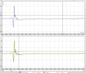
Let's figure out what those wiggles in the tweeter IR are. First I hope we all can agree that the up/down peak is a consequence of the phase rotation of the tweeter, part of it is caused by the filter on the tweeter. However the short waveguide will play a role too.
What I did to find out if the wiggles are related to the dip is the following:
I opened the EQ within REW, and set the bottom view to present the waterfall. As settings for this waterfall plot I chose similar settings as presented before in this thread, though the "Window (ms)" setting was set even shorter at 1 ms.
That gives us this look:
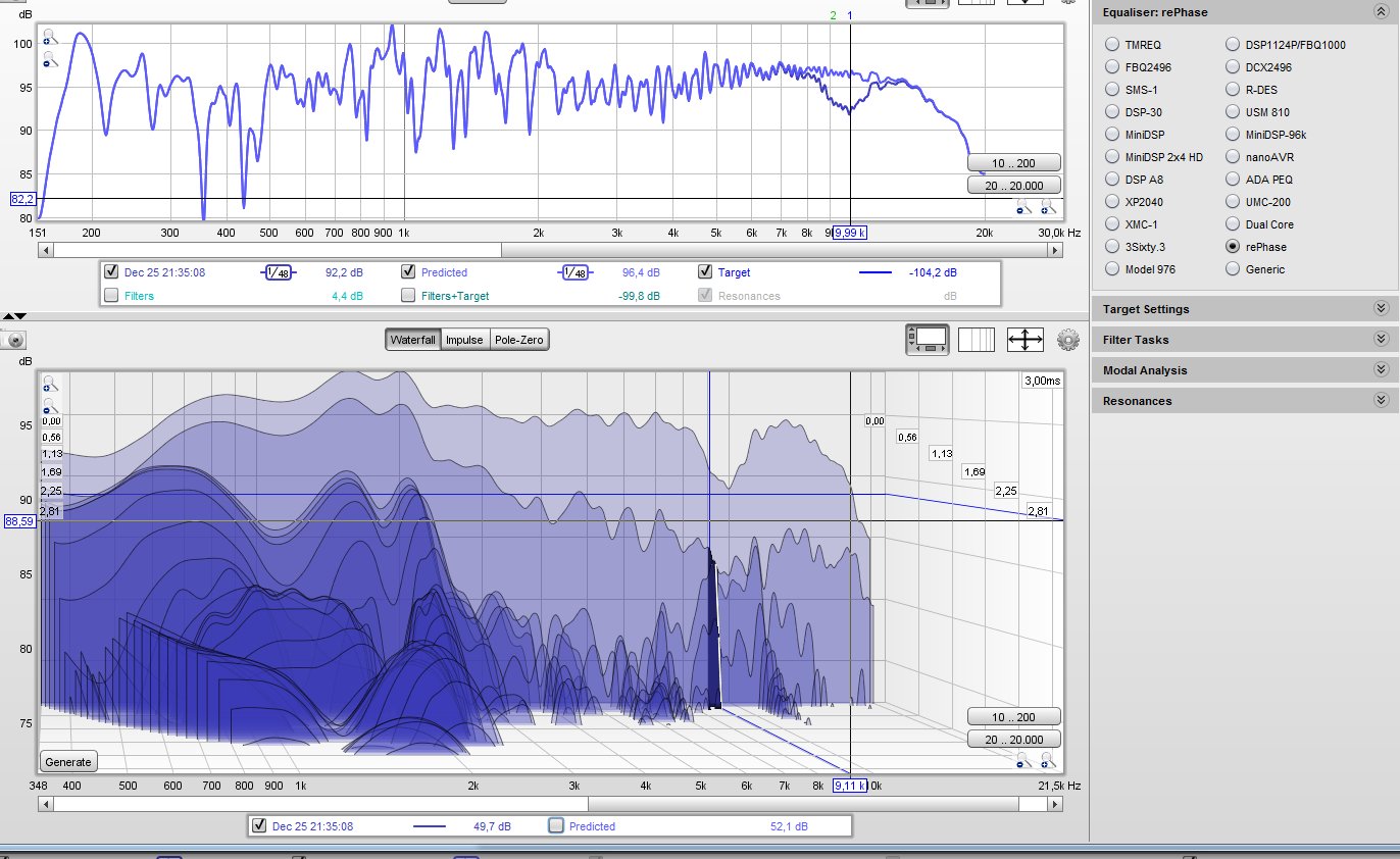
Yeah, the top graph already shows the EQ, however to apply my EQ I actually use the waterfall plot as my guide. The objective: fill that complete dip to restore it into a decent response.
Here's what it looks like with the actual EQ numbers (I chose RePhase as Equalizer):

Going with the notion that speakers are largely following minimum phase behaviour this should fix phase as well, and clean up a decent amount of my IR.
Let's look at the IR tab, instead of the waterfall plot in that bottom window, lets see what result I got:
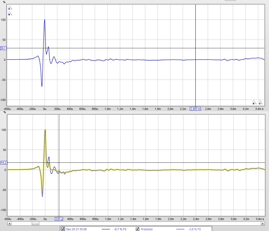
See how this cleans up the majority of bumps in the IR? If I work harder at it, I just might be able to clean it up entirely.
Now this isn't meant as an advertisement for using EQ to clean up the result. This is merely a demonstration that if we took action to get rid of the dip (flush mount the tweeter, maybe that short waveguide would/should benefit from a bigger round-over), the IR will look more clean as well.
Using EQ on something like this would only work if off axis measurements showed the exact same dip at the same place. Fix it acoustically would be my strong recommendation(!)
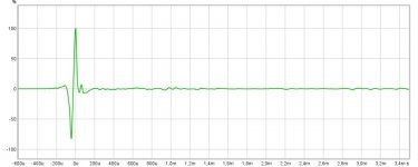
Some other priorities came along over here but a few more tweaks got me this:
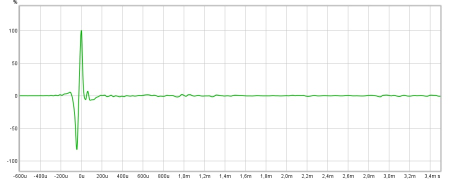
The first peak has been reduced from 32% to 6.6 %, the second is completely gone. Relevant? Only to show all these graphs are linked no matter what. That's what you should take away from this short example.
Time to go for me...
P.S. One more thing to add, by mistake I actually EQ-ed the complete speaker (Woofer + Tweeter, that's the first blue IR)
The last graph is just exporting the EQ and importing it, to apply it to the actual tweeter IR. See how these 2 IR's differ?
That's the woofer's low frequency part added to the tweeter IR.
What I did to find out if the wiggles are related to the dip is the following:
I opened the EQ within REW, and set the bottom view to present the waterfall. As settings for this waterfall plot I chose similar settings as presented before in this thread, though the "Window (ms)" setting was set even shorter at 1 ms.
That gives us this look:
Yeah, the top graph already shows the EQ
, however to apply my EQ I actually use the waterfall plot as my guide. The objective: fill that complete dip to restore it into a decent response.Here's what it looks like with the actual EQ numbers (I chose RePhase as Equalizer):
Going with the notion that speakers are largely following minimum phase behaviour this should fix phase as well, and clean up a decent amount of my IR.
Let's look at the IR tab, instead of the waterfall plot in that bottom window, lets see what result I got:
See how this cleans up the majority of bumps in the IR? If I work harder at it, I just might be able to clean it up entirely.
Now this isn't meant as an advertisement for using EQ to clean up the result. This is merely a demonstration that if we took action to get rid of the dip (flush mount the tweeter, maybe that short waveguide would/should benefit from a bigger round-over), the IR will look more clean as well.
Using EQ on something like this would only work if off axis measurements showed the exact same dip at the same place. Fix it acoustically would be my strong recommendation(!)
Some other priorities came along over here but a few more tweaks got me this:
The first peak has been reduced from 32% to 6.6 %, the second is completely gone. Relevant? Only to show all these graphs are linked no matter what. That's what you should take away from this short example.
Time to go for me...
P.S. One more thing to add, by mistake I actually EQ-ed the complete speaker (Woofer + Tweeter, that's the first blue IR)
The last graph is just exporting the EQ and importing it, to apply it to the actual tweeter IR. See how these 2 IR's differ?
That's the woofer's low frequency part added to the tweeter IR.
Attachments
Last edited:
That's a pretty shoddy way to cover your loudly voiced denunciation of Blauert and Laws.
I assume that I will also have to run for cover for what I am going to post:
It is also my opinion that the figures given by Blauert and Laws are not relevant when it comes to speaker crossovers. Simply because the type of group-delay distortion that they used is differing from the one usually caused by loudspeakers.
Regarding delay perception one has to distinguish between group delay distortion that is usually the same for both channels and a constant interaural delay. Interaural delay is used for lateralisation and therfore we can detect very low values (<20 microseconds).
But the group delay distortion might affect the accuracy (=sharpness) of the lateralisation of a phantom source due to spreading impulses in time as a function of frequency (also called dispersion) with some source material - but not the perception of the actual lateral position.
There was once an iteresting paper by the German IRT dealing with group delay distortion. They came to the conclusion that group-dealy distortion should be below +- 0.2 ms from 0.5 kHz up to 10 kHz. I can't find that paper on their website anymore unfortunately.
Regards
Charles
Charles -...Regarding delay perception one has to distinguish between group delay distortion that is usually the same for both channels and a constant interaural delay. Interaural delay is used for lateralisation and therfore we can detect very low values (<20 microseconds).
But the group delay distortion might affect the accuracy (=sharpness) of the lateralisation of a phantom source due to spreading impulses in time as a function of frequency (also called dispersion) with some source material - but not the perception of the actual lateral position.
There was once an iteresting paper by the German IRT dealing with group delay distortion. They came to the conclusion that group-dealy distortion should be below +- 0.2 ms from 0.5 kHz up to 10 kHz. I can't find that paper on their website anymore unfortunately.
That's (almost) exactly the sort of critique of Blauert and Laws I solicited in an earlier post. The "almost" means we need to see the evidence, as clear as your post writing is.
Funny thing is that as a research-guy, I am actually highly critical of applying lab studies to home audio. That's because sometimes the test conditions are pure, simplified, unblind when blind is needed, or not-quite relevant. Sometimes you get absolute measurements when relative is needed and vice versa. Sometimes we have research conducted by folks who are excellent engineers who are totally inept and botch stuff badly when doing perceptual (psychology) research (and don't know they made a mess).
While B&L appear to have used music and speech as their stimuli, who knows what other errors of testing they may have committed? Or the studies you recall?
Again, an interesting thread but what kind of synchrony is needed and at what cost?
B.
The first peak has been reduced from 32% to 6.6 %, the second is completely gone. Relevant? Only to show all these graphs are linked no matter what. That's what you should take away from this short example.
Nice work wesayso.
Doesn't surprise me at all the eq helped clean up the peaks past the main impulse.
Like you say, the graphs are all linked...completely I say, to no more than mag and phase
If you can get rid of the downward peak prior to the main pulse, I'd love to see that...I haven't a clue there other than adjusting time/polarity.
I don't quite understand what you mean by I'm assuming your original traces are as per factory?
All my measurements are made with drivers mounted onto the box. I do not use factory plots because they are all mounted on IEC panel.
Thanks for the tip. I simply don't have the space for Ground Plane measurements. My lab is very cluttered. It's not only speakers but many power amplifiers too.
Hi Michael, I just meant, were you measuring the box as setup by the factory.
Sorry for the confusion.
Your lab sounds like my workspace...hard as hell to find room to do anything haha.
If I may ask, exactly how are you measuring, speaker / mic position etc ?
Hi Michael, I just meant, were you measuring the box as setup by the factory.
Hi Mark
Not really. I didn't even know the factory provides such info.
I take factory measurements as a rough guide only. Frankly, they don't tell me much. The only way for me is to buy the drivers and test them out. Once I hear them, I can identify their strengths and weaknesses.
If I may ask, exactly how are you measuring, speaker / mic position etc ?
No problem. I'll be happy to share my my work with you. For measurements, I have LMS, OmniMIC and SoundEasy. I use mainly OmniMIC due to convenience. I haven't got the time to play with SoundEasy yet. I understand there are features in there that OmniMic doesn't have.
As for measuring, my mic is 1 meter away, on tweeter axis. Speaker is at least 1 meter from floor. Nothing within a 1 meter radius in front.
With OmniMic, I set the impulse window to 5ms, no smoothing. This will record without reflections down to about 500Hz which is good enough for my needs. My 2-way crossovers are from 2kHz to 4kHz. If I use compression drivers, I don't go below 1kHz.
Hi Michael, if you are not sure if you have done enough or not for the perfect phase / time alignment, there is simple indication that would tell you where you are now. If the phantom center image (such as lead vocal) starts really annoying you, you are above threshold, congratulations. Read Phantom center tread, if you want to know more about it. Most people do not hear it, because the their room and the speakers are far from perfect. "Stereo" is a ridiculously childish technology like a blue and red 3D glasses invented 50 years ago. We adults still follow this illusion today for some reasons, though.
I want to revisit that JBL graph for a while. We might be able to draw up something similar for the speaker in this thread, something to learn from.
Let's review the picture we saw earlier:
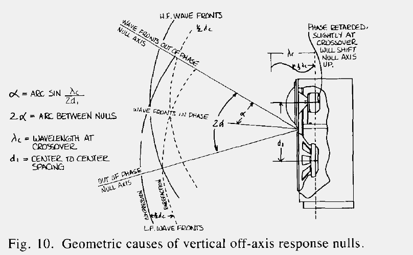
There was a bit of confusion about that design axis. So let's talk about what it is JBL (probably Don Keele) is trying to tell us.
First we take that imaginary line between woofer and tweeter as our design axis. So somewhere on that line we measure the woofer and tweeter. Next we come up with a crossover that puts the output of woofer and tweeter in sync at that measured point on the design axis. OK so far?
Let's review what is seen in this picture. We have 2 sets of arcs. The most left (continuous) arcs cross each other on our design axis.
Behind those continuous arcs is another dashed set. The distance between the two arcs is determined by the frequency at the crossover. How?
The continuous line is the top of our sine shape at the crossover frequency.
The dashed line is the bottom of that sine shape, in other words it is 180 degree out of phase.
By looking at where the dashed line of the woofer hits the continuous line of the tweeter we find the spot where the tweeter will be in phase and the woofer 180 degree out of phase. That is forming the first null the axis.
We can do the same for the other side to see the other null axis form. We would follow the continuous line of the woofer and see where it meets the dashed line of the tweeter.
I would recommend to draw up a similar picture for the speaker in this thread. It would show why the design axis would rise the further away we are from the speaker. At 2m distance the ideal sweet spot would no longer be at tweeter level. Even though it was measured at 1m on that tweeter axis.
So be aware where to measure the speaker, choose your design axis wisely.
Starting from somewhere equal distance to woofer and tweeter will help. No matter if the tweeter is physically as far back as the woofer, draw it up in a picture like this and find out! I'm pretty sure we would like to keep that hard fought time alignment at larger distances. Make sure those null axis are where you want them to be.
Let's review the picture we saw earlier:
There was a bit of confusion about that design axis. So let's talk about what it is JBL (probably Don Keele) is trying to tell us.
First we take that imaginary line between woofer and tweeter as our design axis. So somewhere on that line we measure the woofer and tweeter. Next we come up with a crossover that puts the output of woofer and tweeter in sync at that measured point on the design axis. OK so far?
Let's review what is seen in this picture. We have 2 sets of arcs. The most left (continuous) arcs cross each other on our design axis.
Behind those continuous arcs is another dashed set. The distance between the two arcs is determined by the frequency at the crossover. How?
The continuous line is the top of our sine shape at the crossover frequency.
The dashed line is the bottom of that sine shape, in other words it is 180 degree out of phase.
By looking at where the dashed line of the woofer hits the continuous line of the tweeter we find the spot where the tweeter will be in phase and the woofer 180 degree out of phase. That is forming the first null the axis.
We can do the same for the other side to see the other null axis form. We would follow the continuous line of the woofer and see where it meets the dashed line of the tweeter.
I would recommend to draw up a similar picture for the speaker in this thread. It would show why the design axis would rise the further away we are from the speaker. At 2m distance the ideal sweet spot would no longer be at tweeter level. Even though it was measured at 1m on that tweeter axis.
So be aware where to measure the speaker, choose your design axis wisely.
Starting from somewhere equal distance to woofer and tweeter will help. No matter if the tweeter is physically as far back as the woofer, draw it up in a picture like this and find out! I'm pretty sure we would like to keep that hard fought time alignment at larger distances. Make sure those null axis are where you want them to be.
So be aware where to measure the speaker, choose your design axis wisely. Starting from somewhere equal distance to woofer and tweeter will help. No matter if the tweeter is physically as far back as the woofer, draw it up in a picture like this and find out! I'm pretty sure we would like to keep that hard fought time alignment at larger distances. Make sure those null axis are where you want them to be.
Hi wesayso
Thank you for your advice. I do agree with you the importance of where one should place the design axis. This is particularly important in professional applications like in the JBL illustration.
Presently, my prototype is intended for home use. Even placing the mic on tweeter axis is not the optimal position. I mean, how many people listen with their ears on tweeter axis. Only those that are really keen on audio. For the rest, the tweeters are below the ear.
It doesn't mean that one should abandon sound (no pun intended) engineering principles in designing a loudspeaker. Far from it. It's a more a question of compromises, like how to make a speaker sound good in the hands of the consumers.
Hi Michael, if you are not sure if you have done enough or not for the perfect phase / time alignment, there is simple indication that would tell you where you are now. If the phantom center image (such as lead vocal) starts really annoying you, you are above threshold, congratulations. Read Phantom center tread, if you want to know more about it. Most people do not hear it, because the their room and the speakers are far from perfect. "Stereo" is a ridiculously childish technology like a blue and red 3D glasses invented 50 years ago. We adults still follow this illusion today for some reasons, though.
Hi plasnu
Thank you for the tip. Unfortunately, I don't have the space for phantom center image.
My main purpose with this design was to establish the time arrival between the woofer and the tweeter. With REW, I am able to measure the delay within a 0.02ms tolerance. That's good enough for the time being.
Now that the time-arrival is sorted out, the next item on my agenda is how does it sound. I've been listening to this speaker for at least a week. What is apparent is the absence of harshness in the sibilance. I attribute this to the good phase alignment. But it not the end of this exercise. I'm not too happy with the sound of the tweeter. It is a bit too tame for my liking. Not enough sparkle. I'm not sure whether it's possible but I intend to disassemble the tweeter to check on the ferrofluid. It sounds like the ferrofluid is over-damping the tweeter. If I can access the voice coil, I'll probably remove all the ferrofluid and listen to the H26TG45 tweeter again. Even then, it's not the end. I will be replacing the tweeter with a Morel CAT 378. That would be an interesting comparison. It never ends.
Funny thing is that as a research-guy, I am actually highly critical of applying lab studies to home audio. That's because sometimes the test conditions are pure, simplified, unblind when blind is needed, or not-quite relevant. Sometimes you get absolute measurements when relative is needed and vice versa. Sometimes we have research conducted by folks who are excellent engineers who are totally inept and botch stuff badly when doing perceptual (psychology) research (and don't know they made a mess).
ben, you bring back fond memories.
True story. 20 yrs ago when I started out on audio, my mentor said this to me: "Mike, if you ever go into manufacturing, never hire an "engineer type" designer to design your amps." I looked at him blankly and asked, "What do you mean by engineer type. Isn't that what you want, someone with the necessary qualifications." His rely was "They don't use their ears. They point to the distortion analyzers and insist it's a good design. You need to listen to what you are doing. The analyzers are just instruments."
He should know a thing or two about using one's ears. After all, he was the owner of Robertson Audio and he hired the legendary John Iverson to design the Robertson Forty Ten and Sixty Ten.
I found this thread quite interesting so I will put up a few comment from my own experience.
The human ear and brain is a rather interesting thing. It can be selective, it can fill in the blanks etc.
However, some scientists in the know with research suggest time alignment is most sensitive in the 2000 hertz region.
Oddly enough that is in the zone where most conventional 2 way domestic loudspeakers have a crossover point to a woofer and tweeter.
Assuming you have the acoustic centres of the drivers aligned and you have gotten the crossover design correct by the measured the phase tracking of the crossover in a simulator like LinearX Leap 5 there could still be unforeseen audible problems.
1. If the tweeter cannot be located very close to the woofer the relative time alignment will only be true for one measurement location and one listening location.
This can be a difficult problem in practical terms due to the diameter of the tweeter top plate. However, there are some very good tweeters without a top plate that allows very close placement to the woofer.
In a practical design like the Legend Audio (no association) Kantu 6 the designer Rod Crawford has paid great attention to the proximity of the tweeter to the mid cone.
2. As noted in previous posts the location of the axis of the relative acoustic centres of both the woofer and the tweeter will impact on lobbing in the crossover region. If the lobe of the tweeter is pointed to an early reflection point then that reflection point will cause a smearing of the spatial transient performance due the delay in the early reflections. This could be off the baffle, the frame of the woofer etc.
The lobes can be manipulated by choosing the slopes of the crossover design, i.e. LR 4th order (combined acoustic and voltage drives from the crossover filters) to control where the lobe is directed.
Hi plasnu
Thank you for the tip. Unfortunately, I don't have the space for phantom center image.
My main purpose with this design was to establish the time arrival between the woofer and the tweeter. With REW, I am able to measure the delay within a 0.02ms tolerance. That's good enough for the time being.
Now that the time-arrival is sorted out, the next item on my agenda is how does it sound. I've been listening to this speaker for at least a week. What is apparent is the absence of harshness in the sibilance. I attribute this to the good phase alignment. But it not the end of this exercise. I'm not too happy with the sound of the tweeter. It is a bit too tame for my liking. Not enough sparkle. I'm not sure whether it's possible but I intend to disassemble the tweeter to check on the ferrofluid. It sounds like the ferrofluid is over-damping the tweeter. If I can access the voice coil, I'll probably remove all the ferrofluid and listen to the H26TG45 tweeter again. Even then, it's not the end. I will be replacing the tweeter with a Morel CAT 378. That would be an interesting comparison. It never ends.
High on my list would be to fix that dip at 10 kHz... It probably will brighten up the sound of that tweeter.
Hi wesayso
Just as I thought. The ferrofluid is the culprit. After I removed the ferrofluid, the speaker comes alive. The vocals jump out and the bass is in tandem with the rest of the music. This is the kind of reproduction I expect from my speakers. With the ferrofluid, the speaker sounded no better than background music in shopping malls. No kidding.
For the benefit of those who would like to remove the ferrofluid, the first step is to remove the 3 metal clips that hold the waveguide to the magnet. Simply pry out the clips with a small screwdriver. Lift the waveguide, then gently lift the diaphragm/voice coil assembly. You will now have access to the gap. I inserted strips of paper to soak up most of the ferrofluid. After that, I applied some Ronsonol lighter fluid on the paper to clean out all remnants of the ferrofluid. Don't forget to remove the ferrofluid on the voice coil and the underside of the collar. Re-assemble and the H26TG45 will sing.
1. If the tweeter cannot be located very close to the woofer the relative time alignment will only be true for one measurement location and one listening location.
Hi macka
That is my assessment too.
- Status
- This old topic is closed. If you want to reopen this topic, contact a moderator using the "Report Post" button.
- Home
- Loudspeakers
- Multi-Way
- What is Time-Alignment