I'm guessing Troels is unhappy with what he perceived to a colouration just under the crossover point of his design, rather than the frequency response. Hence why he designed a 3 way with the 2" accuton. I think its a matter of taste, some may like the 'lush' sound of a paper cone being used in that region. I've heard similar critique about the satori 6.5" when crossed above a certain point.
If the baffle were curved a la magico, wd that help? I'm guessing the baffle plays a role with that rise above baffle step
Download something like Edge and play with it
") In short - it depends. It might be a contribution of the loudspeaker driver itself or a baffle step effect. If it is the second, yes, a roundover/chamfer do the trick with the second being somewhat cheaper to implement (bits are cheaper) but for best results 2 or 3 consecutive chamfers (creating a curved like surface) are needed. Small roundovers of 1/2" or so have very little effect (but have some). At about an inch you`re floating, better if they`re 2" or bigger. Another trick is to offset the drivers but it is not as visually appealing to some as centered drivers. Third aproach which works for small drivers only is a very narrow baffle where you could push the first baffle diffraction bump and consecutive dip above the crossover frequency. I`ve never been able to do this with drivers bigger than 5" or so. Problem is, what is somewhat doable is a roundover of about 1 1/4" at most and that would require your router ot be put on a table, the bits are really big and scary when they rotate even at 10k rpm. Bigger roundovers I believe would need a slice based structure, so either a CNC router and a large amount of MDF sheets or to have a steel template cut by a CNC and then use it with a quality router and a bearing cutter (I saw the idea from a forum member on here, Wesayso, so redit to him) are the options. That means lots of cutting so router must be of good quality and you`d spend some good money on bits.
In short - it depends. It might be a contribution of the loudspeaker driver itself or a baffle step effect. If it is the second, yes, a roundover/chamfer do the trick with the second being somewhat cheaper to implement (bits are cheaper) but for best results 2 or 3 consecutive chamfers (creating a curved like surface) are needed. Small roundovers of 1/2" or so have very little effect (but have some). At about an inch you`re floating, better if they`re 2" or bigger. Another trick is to offset the drivers but it is not as visually appealing to some as centered drivers. Third aproach which works for small drivers only is a very narrow baffle where you could push the first baffle diffraction bump and consecutive dip above the crossover frequency. I`ve never been able to do this with drivers bigger than 5" or so. Problem is, what is somewhat doable is a roundover of about 1 1/4" at most and that would require your router ot be put on a table, the bits are really big and scary when they rotate even at 10k rpm. Bigger roundovers I believe would need a slice based structure, so either a CNC router and a large amount of MDF sheets or to have a steel template cut by a CNC and then use it with a quality router and a bearing cutter (I saw the idea from a forum member on here, Wesayso, so redit to him) are the options. That means lots of cutting so router must be of good quality and you`d spend some good money on bits.
Last edited:
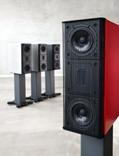
Cheers for all.info! The stepped baffle is such an ugly thing, but i like the way Raidho get around this, with a shallow waveguide and an ingenious angled baffleDownload something like Edge and play with it
Cheers for all.info! The stepped baffle is such an ugly thing, but i like the way Raidho get around this, with a shallow waveguide and an ingenious angled baffle
Well Raidho has the resource to try out all sort of baffles. I don't have that much wood and time. If I use slanted baffle, I probably go with a fix 7.5 degree and see what happens.
Sorry Andy didnt realise we were continuing a discussion.Well Raidho has the resource to try out all sort of baffles. I don't have that much wood and time. If I use slanted baffle, I probably go with a fix 7.5 degree and see what happens.
cad it up quickly and get it cnc'd. V easy, cheap and saves lots of time.
As there was really no excuse not to, I learnt basic cad just for speaker building.
The stepped baffle is such an ugly thing
Sorry, I might have misunderstood your question, my post concerned edge diffraction (also applicable to the physical Z-dimension offset created with an extra piece of MDF for the woofer). The problem with the latest build of TG in terms of offseting is this massive edge in close proximity to the tweeter. I have done it and it creates a substantial ripple, so went for a slanted design. Not sure why it was done this way, in the majority of his other designs it was slanted. I suspect the reason to be a desire to mount the drivers closer to each other. With a small waveguide like in the Raidho example, you will control the tweeter beam to a certain frequency, a 17cm waveguide (around 6.5") would loose control somewhere below 2Khz where the wavelength becomes too long so you will still get this diffraction. But here`s the catch - if you go for a shallow 16-20cm waveguide like the Monacor WG300 or the newer Visaton WG148 which was used with great effect in Zvu`s project somewhere on the forum, the waveguide is deep enough to provide the physical offset alone so no need for any extra work. I`m still not sure why popularity of waveguides is so low with commercial designs, they solve a lot of problems.
Last edited:
I`m still not sure why popularity of waveguides is so low with commercial designs, they solve a lot of problems.
V true esp in 2 ways
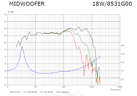
We had a thread a while back about merlinx76' problems with the ZRT 2.5 Zaph design. A poor and overly simplistic and low filter with a difficult 18W8531G00 driver, IMO. And I DO have the FRD and ZMA files for this driver direct from Zaph himself.
Erik mercilessly trolled it with his opinion that the 4 ohm 18W4531G00 is great in an MT. It didn't help at all, because that is a very different animal from a poorly implemented 2.5 way.
Now I am having to suffer his gibes that only I and Troels Gravesen find the 18W8531G00 difficult. It actually isn't too hard if you have the right idea. But, TBH, I'm not sure Erik has the right idea at all. 6dB slope with a 4kHz notch? Really? Best you can do?
Attachments
Steve,
I brought your name up here out of respect and completeness. I really don't feel I have mercilessly trolled you or anyone else. I have been just as stubborn about my opinion as you are of yours, and as I have pointed out, I strongly suspect there has been an undocumented engineering change as the spec sheet and the drivers I have in front of me (sounding great) simply do not match.
As for the 1st order electrical that you point out, that proves my point that this driver is easy as cake to use. If this driver was nearly as difficult as described by others who do not have the drivers in hand such a gentle slope would never have worked.
Best,
E
No, you still aren't listening, Erik.
The Scan woofer might work OK on a 6dB, but actually gets much harder on 12dB or even 18dB. We are, after all, not in the business of building LGWAG speakers. We want to be able to play Mendelssohn's Elijah!
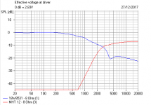
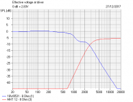
You have also missed a trick with the whole concept. This is how you do $500 ribbons with series wired 4 ohm bass for the tidy higher impedance and good dispersion:

Happily, I feel confident a 2.5kHz+ crossover is possible here. Impedance takes a beating, but that is what happens with ill-behaved drivers that force you to depart from optimal values. TBH, I think a Peerless 830874 or 830875 would make more sense. The poly dustcap works better than anything paper. More damping, you see.
The Scan woofer might work OK on a 6dB, but actually gets much harder on 12dB or even 18dB. We are, after all, not in the business of building LGWAG speakers. We want to be able to play Mendelssohn's Elijah!
You have also missed a trick with the whole concept. This is how you do $500 ribbons with series wired 4 ohm bass for the tidy higher impedance and good dispersion:
Happily, I feel confident a 2.5kHz+ crossover is possible here. Impedance takes a beating, but that is what happens with ill-behaved drivers that force you to depart from optimal values. TBH, I think a Peerless 830874 or 830875 would make more sense. The poly dustcap works better than anything paper. More damping, you see.
Happily, I feel confident a 2.5kHz+ crossover is possible here.
If you`re talking about the Scanspeak + Mundorf project subject to the thread (sorry, got confused a bit and flu`s taking the upper hand) - I still use the 4 ogm version of the woofer crossed at 2.5Khz and I don`t like it. It beams like hell and moving slightly offaxis (like at 30-40 degrees) changes the sound. I am too lazy to rework these and don`t see any future in upgrading them either so not bothering for now and will not bother with them, but as a summary - this woofer becomes directional above 2Khz, quite a bit in my opinion and its cone/suspension is too heavy to be used even up to 2Khz (majority of other 7" drivers hld similar MMS). It ould be great if used as a channel filler, inbetween a quality large woofer and a coaxial CD loaded horn or helped by an upper midrnage dirver, like a 13-16cm Supravox or one of the newer Satori mids.
Mario,
Perhaps the beaming issue is why Troels gave up on using this as a mid-woofer and why I completely avoided the issue? I never attempted a 2.5 kHz crossover point, so have no idea how it would sound.
I am listening to the SNR-1 as I type and I have to say, I can't hear any reason at all to change a thing. I cannot hear the woofer or tweeter as separate, there's no audible disconnect between the midrange and treble, and off axis they sound great. If anything, I do think they sound better in front of the mid than the tweeter. I would not call that a design fail though (see discussion on stepped baffles). They sound quite good off both axis.
These Mundorf AMT's are also pretty incredible. I literally cannot measure compression between 70 and 90 dB of output, and distortion is vanishingly low at the bottom, and their power handling is ridiculous. I have to look at the spec. If I had used their smaller brethren then of course a higher crossover might be de rigeur.
Best,
E
Perhaps the beaming issue is why Troels gave up on using this as a mid-woofer and why I completely avoided the issue?
I never attempted a 2.5 kHz crossover point, so have no idea how it would sound. I am listening to the SNR-1 as I type and I have to say, I can't hear any reason at all to change a thing. I cannot hear the woofer or tweeter as separate, there's no audible disconnect between the midrange and treble, and off axis they sound great. If anything, I do think they sound better in front of the mid than the tweeter. I would not call that a design fail though (see discussion on stepped baffles). They sound quite good off both axis.
These Mundorf AMT's are also pretty incredible. I literally cannot measure compression between 70 and 90 dB of output, and distortion is vanishingly low at the bottom, and their power handling is ridiculous. I have to look at the spec. If I had used their smaller brethren then of course a higher crossover might be de rigeur.
Best,
E
Last edited:
why I completely avoided the issue?
Look, I admire your interest and all you`ve achieved for yout age but if you want a piece of advice, you may consider the option of being a bit more humble when it comes to your own works.
I have and will abstain of commenting your design here, but if you are interested to know what I think of it, PM me.
Mario,
I hope that in 2018 you find someone who makes you laugh as much as you make me.
All the best,
Erik
Mario,
I hope that in 2018 you find someone who makes you laugh as much as you make me.
All the best,
Erik
I guess I am not the only one being accused of "not humble".
I'm guessing Troels is unhappy with what he perceived to a colouration just under the crossover point of his design, rather than the frequency response.
If this driver was nearly as difficult as described by others who do not have the drivers in hand such a gentle slope would never have worked.
Easy/difficult is subjective.
When we have worked with many drivers, we would have many references, benchmarks and standards. If we worked with $600 drivers and it doesn't sound any better than our $500 drivers then we would normally think that it is a failure. (OTOH, the opposite is true). TG has also higher standard now regarding sound neutrality than he did long time ago.
If 3-way will improve the sound considerably, why the 2-way floorstanding? Two-way like Erik's seems to me a better option as bass response is so impressive. But lower crossover point will be easy if the tweeter is changed.
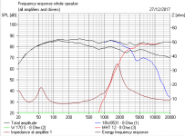
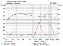
Looking from the SNR-1 bass response, if only we can believe it 100%, Erik has no midrange hump around 700 Hz. This is possible but only measurement can tell the truth.
But speaker design is not about how to put the drivers in their comfort zones. More important is that both drivers must work in synergy. This is difficult, especially in marrying such a woofer to an AMT.
What this thread lacks is quality measurements.
Gated measurements from 1-2m with gate set at <300Hz would clear things up. Measurements posted here are not measurements at all but simulation from Xsim.
On axis and of axis (0, 15, 30, 45 and 60 deg) measurements are needed to be able to see anything. These are too low resolution aproximations of real measurements.
Other than that, i compliment the effort to make something for the diy crowd.
Cheers
Gated measurements from 1-2m with gate set at <300Hz would clear things up. Measurements posted here are not measurements at all but simulation from Xsim.
And it is not even noted how the measurement curves were derived and under what circumstances/settings, neither is mentioned what setup was used and whether it was calibrated or not.
On axis and of axis (0, 15, 30, 45 and 60 deg) measurements are needed to be able to see anything. These are too low resolution aproximations of real measurements.
Cheers
He will not post these even if he has them because they will reveal what is known as a Klingon Bird of Prey sonogram. The chosen crossover frequency (not sure why) is too high for the 18W and the AMT has high dispersion there. Besides, the transition from an MMS of 18gr to an AMT will be audible, as noted by a post above. This is why on the posted simulations tweeter level is recessed by a whopping 5db (no wonder why they were described as warm sounding because its the woofer that dominates) and on these measurements the woofer appears with much higher smoothing than the tweeter. The asymmetrical crossover used I would be curious to see how would do in the vertical plane. And then 88db from this woofer indicate low bsc applied (evident by a small 1mH coil), if these are to be placed close to a wall or used with a sub - fine. They present a moderate load to an amp - about 4ohms at 140Hz and phase at -15 degrees.
I don`t see impulse and step response either.
- Home
- Loudspeakers
- Multi-Way
- SNR-1 : Mundorf / Scanspeak 2 Way