Hi David,
Well, never did a real detailed comparison here. That's why I write 'better', as I can't specify it exactly. I felt that results were more accurate when using GMSH vs the internal mesher, especially when simulating horn profiles, phaseplugs etc. - i.e. complicated surfaces.
May be we'll learn more here from Dons experiment...
Another reason to go with GMSH for me is that I do separate meshes for the e.g. membrane, phaseplug, horn profile and enclosure with different resolution and import different meshes to ABEC then. E.g. the backside of an enclosure does not have to have the same fine resolution than the membrane. Can safe a bit calculation time as well.
BW,
Christoph
As someone that doesn't use ABEC for BEM solutions I haven't posted earlier but may be able to help a bit with the meshes.
Representing the geometry as a collection of flat triangles rather than a collection of curved surfaces (usually NURBS these days but occasionally something else) is a crude approximation. If you pass a set of coarse triangles as the base mesh and then refine that mesh the geometry will be as crude if not worse than the initial crude mesh. The finer mesh will resolve higher frequencies within the solution region but many of the (x,y,z) coordinates will not lie on the correct smoothly curved geometry.
When you generate a triangular mesh you should always do it using the correct smooth geometry so that all the vertices of the triangular mesh lie on the correct geometry. If you want a finer mesh go back and generate a finer mesh on the correct smooth geometry and don't refine a coarse triangular mesh.
What do you use?As someone that doesn't use ABEC for BEM solutions I haven't posted earlier...
...but may be able to help a bit with the meshes...
Yes, that definitely helped, thanks.
Best wishes
David
Last edited:
The last free code I used was Acousto (link not working at the moment but probably a temporary source forge problem) for speaker cabinet radiation. It has been discussed here before. In terms of modelling it is fairly similar to ABEC but has the significant advantage for projects of any significant size of coming with source code enabling interfacing to it and extending/fixing it. It lacks elements of a reasonable and higher order (important for smooth solutions that are hitting memory and/or cpu limits) and a method of grouping closely coupled elements while approximating the coupling to further away loosely coupled elements (can greatly reduce required computing resources with suitable geometries at the cost of a negligible to small drop in accuracy).What do you use?
The free code before that was Elmer but this failed an initial symmetry check (never assume codes work as advertised!) and when I looked at how the project handled software quality and maintenance I decided it wasn't one I would be happy to work with in the longer term and didn't find and fix whatever was wrong.
There is a fair amount of BEM software around but all the good stuff I am aware of is commercial. Mind you the last time I looked was a few years ago now so it might be different today.
The last free code I used was Acousto...
Thanks for the info, I was not familiar with it and it looks quite impressive.
But ABEC looks to be the DIY default and it certainly is helpful to have other people's experience to call on.
The free code before that was Elmer...failed an initial symmetry check (never assume codes work as advertised!)
Oh yes...Software was my trade, mainly mathematical stuff, I know all about that assumption.
and when I looked at how the project handled software quality and maintenance I decided it wasn't one I would be happy to work with...
And that.
Best wishes
David
Yes, seems funny. However, I'm quite sure you'll subscribe that after done some projects...
Only natural that it will become more familiar.
But it really needs a better introduction and tutorial in the help.
It looks to be almost all the work of J. Panzer, an extraordinary achievement for one person.
But he is too close to see it as a newbie does, my first recommendation is a "Hello World" style example, a circular piston in an infinite baffle maybe.
At least I am past the initial steps, to the point I can now have fun with experiments.
Thanks Christoph, and everyone else, for the help to reach this.
Best wishes
David
Last edited:
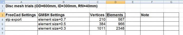
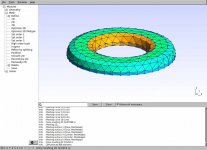
Mesh 1 - GMSH element size
Back to mesh comparisons.
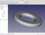
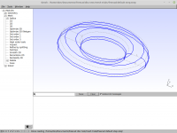
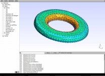
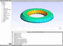
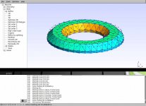
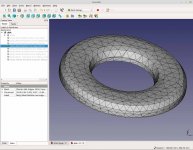
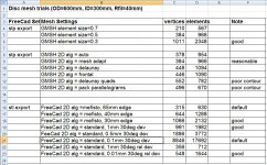
I'm using a large disk [ OD=600mm, ID=300mm, R=40mm ] to create a curvy surface with some flat sides. It should exaggerate issues with meshing and has polar symmetry to (hopefully) make spotting defects easier.
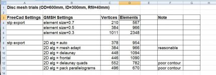
The first comparison is FreeCad stp to GMSH to try a few GMSH settings to see how it affects the mesh quality and size. The starting point are Gaga's previous settings (element size =0.5) as they seem very good. Freecad does not have any adjustment parameters for the stp export. The GMSH meshes use element size [0.7, 0.5, 0.3], and the result is very sensitive to this parameter. I like Gags's suggestion to try 3 sizes and pick one that's suitable. The results are in the table.
Back to mesh comparisons.
I'm using a large disk [ OD=600mm, ID=300mm, R=40mm ] to create a curvy surface with some flat sides. It should exaggerate issues with meshing and has polar symmetry to (hopefully) make spotting defects easier.
The first comparison is FreeCad stp to GMSH to try a few GMSH settings to see how it affects the mesh quality and size. The starting point are Gaga's previous settings (element size =0.5) as they seem very good. Freecad does not have any adjustment parameters for the stp export. The GMSH meshes use element size [0.7, 0.5, 0.3], and the result is very sensitive to this parameter. I like Gags's suggestion to try 3 sizes and pick one that's suitable. The results are in the table.
Attachments
Last edited:
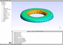
Mesh 2 - mesh algorithm
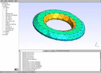
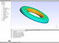
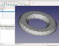
The element size = 0.5 is constant while the algorithms were changed to check sensitivity.
The pics (left to right) are [ Auto, MeshAdapt, Delaunay, DelaunayQuad, Frontal, Parallelogram]. Gaga's preference [MeshAdapt] seems to be good. The table lists the comparison, and there is moderate #element size variation and the quality does vary.
Attachments
-
 gmsh 2D alg pack parallelogram.jpg118.2 KB · Views: 58
 -
 gmsh 2D alg frontal.jpg120.5 KB · Views: 53
 -
 gmsh 2D alg delaunay quad.jpg121.6 KB · Views: 58
 -
 gmsh 2D alg delaunay.jpg122.4 KB · Views: 55
 -
 gmsh 2D alg mesh adapt.jpg119.2 KB · Views: 65
 -
 gmsh 2D alg auto.jpg120.8 KB · Views: 60
 -
 gmsh algorithm compare.jpg129.9 KB · Views: 70
Last edited:
Good to see the mesh study and to add a few comments:
- Quadrilateral elements are almost always preferable to triangular in terms of accuracy but the strength of the preference will depend on the type of element being used.
- The shape of the elements affects the accuracy but again the amount will depend on the type of element being used. In regions where quadrilaterals are strongly non-rectangular they lose accuracy and a mesh of fairly uniform triangles may be preferable. Thin triangles and particularly slivers are poor and can cause some codes problems.
- The variation in size affects the accuracy although this is trumped by strong variations in the solved quantities. That is, it is almost always more important to have small element edges to resolve strong gradients in the solved quantities than it is to keep the element sizes uniform.
- Almost all engineering mesh generators will inspect a mesh and write out a range of metrics describing the quality, for example. This is particularly useful for locating regions of poor elements and then changing the meshing parameters to improve things.
- Something to be aware of is that numerical edges and physical edges are the same thing to a solver. They can also show up in 3D prints of STL files if the triangles are not fine enough and particularly if the mesh generator aligns the triangles to bring out coherent edges. For a waveguide this means the edges of the triangles lining up to create circular/elliptical edges where the curvature is steepest. It might look nice and neat but randomising the errors so they add and subtract rather than all sum in the same way is preferable. The Delaunay algorithm should avoid this but I would suggest checking the other algorithms.
- Enlarging the curved section on the test case might be helpful in order to be more representative of the large curved section of a waveguide.
Good to see the mesh study and to add a few comments:
A delayed start, as life gets in the way.
")
- Quadrilateral elements are almost always preferable to triangular in terms of accuracy but the strength of the preference will depend on the type of element being used.
- The shape of the elements affects the accuracy but again the amount will depend on the type of element being used. In regions where quadrilaterals are strongly non-rectangular they lose accuracy and a mesh of fairly uniform triangles may be preferable. Thin triangles and particularly slivers are poor and can cause some codes problems.
- The variation in size affects the accuracy although this is trumped by strong variations in the solved quantities. That is, it is almost always more important to have small element edges to resolve strong gradients in the solved quantities than it is to keep the element sizes uniform.
Good to keep in mind. What I'm seeing is flat surfaces getting large elements because there is little surface deviation. The meshing algorithm would need to have a max edge length to breakup large flat surfaces.
- Almost all engineering mesh generators will inspect a mesh and write out a range of metrics describing the quality, for example. This is particularly useful for locating regions of poor elements and then changing the meshing parameters to improve things.
- Something to be aware of is that numerical edges and physical edges are the same thing to a solver. They can also show up in 3D prints of STL files if the triangles are not fine enough and particularly if the mesh generator aligns the triangles to bring out coherent edges. For a waveguide this means the edges of the triangles lining up to create circular/elliptical edges where the curvature is steepest. It might look nice and neat but randomising the errors so they add and subtract rather than all sum in the same way is preferable. The Delaunay algorithm should avoid this but I would suggest checking the other algorithms.
- Enlarging the curved section on the test case might be helpful in order to be more representative of the large curved section of a waveguide.
Thanks for the link, I'll have a look. Valid point that aligned edges could create a bias compared to a random (assumed) unbiased alignments. My first inclination would have been to align everything and make it symmetrical.
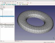
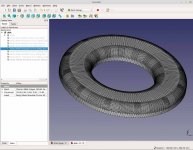
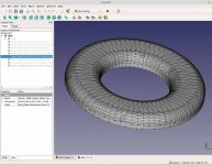
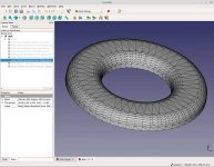
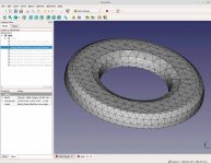
Mesh 3 - FreeCad stl
FreeCad also exports stl and has a few control parameters. We can compare this design path to the previous mesh posts (#129, #130) using stp export and GMSH. The comparison should be between meshes of similar #elements as this determines ABEC solve time.
I'm using FreeCad 0.17 and it has 2D algorithms [Standard, Mefisto] and [MaxEdge, Abs, Rel] surface deviation. It looks like NetGen is also planned however its greyed out (unavailable) on v0.17. The default settings in FreeCad mesh do not provide good results for my disk (ring). The default Standard has too many elements, and the default Mefisto is too coarse with too few elements. I've listed the summary and some screen shots of the results.
Approx 2000 elements provides a good surface for both the mesh generators. This would allow a fair comparison when they are imported into ABEC for trials. It's also a good reference point when we try to shrink them down and maintain a good surface representation.
Attachments
-
 freecad stl std 0.01mm 30deg rel dev.jpg179 KB · Views: 49
 -
 freecad stl std 1mm 30deg rel dev.jpg168 KB · Views: 57
 -
 freecad stl std 0.1mm 30deg dev.jpg241.3 KB · Views: 60
 -
 freecad stl std 0.5mm 30deg dev.jpg213.1 KB · Views: 173
 -
 freecad stl std 1mm 30deg dev.jpg196 KB · Views: 176
 -
 freecad stl mefisto 30mm edge.jpg182.1 KB · Views: 178
 -
 freecad stl mefisto edge 40mm.jpg179.9 KB · Views: 175
 -
 freecad stl mefisto 65mm edge max.jpg153 KB · Views: 184
 -
 freecad algorithm compare.jpg258.6 KB · Views: 61
Last edited:


I don't use gmsh, abec, freecad,... but do sometimes use acousto, salome,... Is there interest in creating a representative test case for assessing various simulation packages and storing a set of files somewhere for people to get going with software packages like these?
What are the thoughts on perhaps a 1" tweeter, 6.5" midwoofer, 350 x 250 x 250 mm cabinet, geometrical simple elliptical waveguide on the tweeter? Geometry of waveguide? Conical, conical with radius, ellipse? Tweeter not offset to give one plane of symmetry. Geometry of tweeter? Geometry of midwoofer?
If there is a bit of interest here perhaps starting a new thread may be wise.
... a representative test case...
What do you have in mind to assess the test case?
For speed of solution, accuracy, or more as a test of usability, and as a demonstration?
Don's excellent experiments show how much variation is possible in even a simple geometry.
So I plan to start simple, with an OS waveguide, partly because an analytical, closed form solution is known, so the results can be compared.
I also plan to do the classic "piston in an infinite baffle" for similar reasons, and also to compare with OS (a personal interest)
Best wishes
David
What do you have in mind to assess the test case?
For speed of solution, accuracy, or more as a test of usability, and as a demonstration?
The intention was to have it as a first/early test case for anyone performing detailed speaker simulations or developing speaker simulation software. Therefore it needs to be representative of speaker simulations and the geometry needs to be unambiguous and straightforward to define.
Don's excellent experiments show how much variation is possible in even a simple geometry.
Yes Don's experiments prompted the suggestion. What he is doing if repeated by others would be useful but his grid is not representative of all the kinds of things a grid for a speaker would need to handle. The next person doing something similar would almost certainly pick a different test case. But if the test case was a (simple) speaker then it is much more likely to get picked up as a test case by others and particularly if a few people have already used it.
So I plan to start simple, with an OS waveguide, partly because an analytical, closed form solution is known, so the results can be compared.
Not keen because the more useful waveguides are elliptical/rectangular rather than circular both to reduce centre line diffraction effects and to get different behaviour in the vertical and horizontal planes. They also have a tweeter in the middle and transition smoothly (usually) to the baffle. However, an ellipse projected along an elliptical path would be fine.
I also plan to do the classic "piston in an infinite baffle" for similar reasons, and also to compare with OS (a personal interest)
Analytical solutions don't exist for a representative speaker geometry. The approach for test cases of this kind is to perform a very highly resolved simulation and use this as the reference solution when checking the behaviour of simulations on practical grids.
Your test cases are simpler than what I am suggesting and I think are being performed for a slightly different purpose. The test case I am suggesting should contain everything relevant for a speaker simulation but in the simplest form that is practical.
I don't use gmsh, abec, freecad,... but do sometimes use acousto, salome,... Is there interest in creating a representative test case for assessing various simulation packages and storing a set of files somewhere for people to get going with software packages like these?
ABEC3 already has a number of example speaker designs that are intended to "instruct" the novice. I found this route to be a steep learning curve because I was always trying to deduce what was happening. The manual's command syntax and some examples are not a replacement for a tutorial. Eventually you will catch on but it was not easy. So my vote is for video tutorial for new users.
The trials I've been supplying are just intended to support a comparison of design paths going into ABEC3. The time spent in the design cycle and the solving time can vary tremendously so its worth evaluating these mesh variables on simple structures. Next trial will include ABEC3.
- Status
- This old topic is closed. If you want to reopen this topic, contact a moderator using the "Report Post" button.
- Home
- Loudspeakers
- Multi-Way
- ABEC experts - help!