OK, here is how I actually use Gmsh.
Disclaimer 1: I'm using version 3.0.4 for OSX, other versions might look a bit different.
Disclaimer 2: This may not be the best option to mesh for all situations. I just works fine for me.
Disclaimer 3: You probably know most of the steps. I explain in some detail anyway in order to make it clearer for ABEC beginners....
Here we go.
The respective *.step-file has been opened in Gmsh.
I then apply following settings choosing 'Tools' and 'Options'.
Options 1
Within the 'Options' Window I choose 'Mesh' - 'General' and
- 'MeshAdapt' as 2D algorithm:
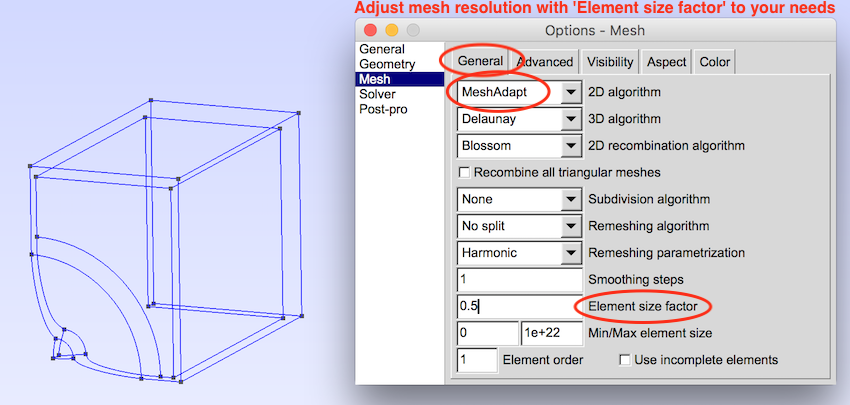
Moreover I define the mesh-resolution here by giving a number for the 'Element size factor'. The lower the number, the higher the resolution of the mesh.
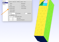
Options 2
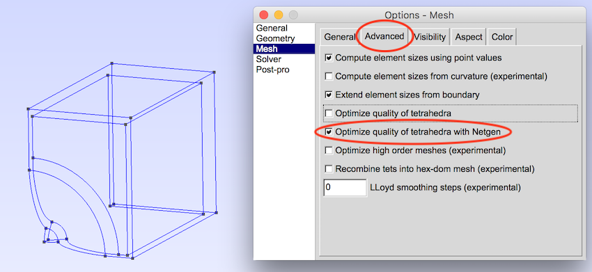
Before meshing, I select 'Optimize quality of tetrahedra with Netgen' under 'Tools' - 'Options' - 'Mesh' - 'Advanced':
Mesh

I do meshing via 'Mesh' - '2D'
Surface numbers
Surfaces labels can be seen choosing 'Surface labels' under 'Options' - 'Geometry' - 'Visibility'
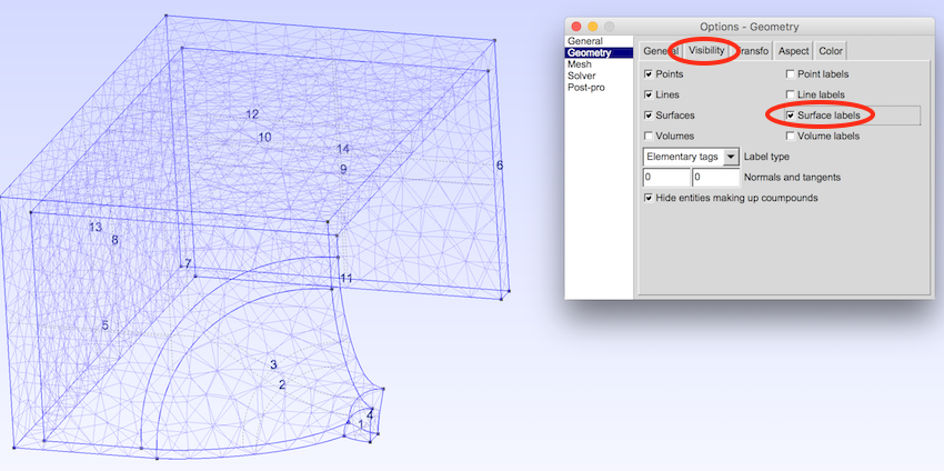
You'll need these numbers in the 'Elements' Script in ABEC in order to reference the respective surfaces.
Save mesh:
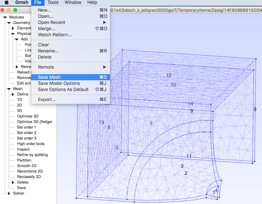
Not much to comment here. The mesh file can then be imported to ABEC. The size of the 'XY.mesh' file gives a good indication on how long your computer will need to solve the file in ABEC.
Hope this helps.
Christoph
Thank you, I'd be hopeless without this post.
I have two questions:
1) When I open a STEP file in GMSH, I see a wireframe. How can I see a solid? I've tried setting that in "options" but it doesn't make a difference. It's as if GMSH thinks the model isn't a solid.
2) what's the best way to define physical groups? I know you can do it in GMSH, but it seems like it might be faster to define then in FreeCad or Fusion360.
Hi Patrick,
Not sure, if I got your question right...
I assume 'wireframe' means an image like the first one shown in the cited quote? If so, that's exactly what I see when I open *.step-files in GMSH. However, GMSH still recognizes areas between 'wires' or 'edges' as surfaces. You see that as soon as you choose 'Surface labels' from 'visibility' and the respective numbering of surfaces pop up.
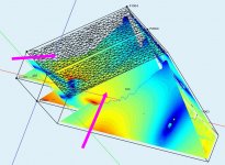
If you want to see 'solid' surfaces, you can do this after you meshed the model by using the option 'mesh' - 'visibility' - 'surface faces'. Looks like this for example:

I did not work with the 'physical groups' feature in GMSH. Just used the surface numbering to work with in the ABEC script.
I have two questions:
1) When I open a STEP file in GMSH, I see a wireframe. How can I see a solid? I've tried setting that in "options" but it doesn't make a difference. It's as if GMSH thinks the model isn't a solid.
Not sure, if I got your question right...
I assume 'wireframe' means an image like the first one shown in the cited quote? If so, that's exactly what I see when I open *.step-files in GMSH. However, GMSH still recognizes areas between 'wires' or 'edges' as surfaces. You see that as soon as you choose 'Surface labels' from 'visibility' and the respective numbering of surfaces pop up.
If you want to see 'solid' surfaces, you can do this after you meshed the model by using the option 'mesh' - 'visibility' - 'surface faces'. Looks like this for example:
I did not work with the 'physical groups' feature in GMSH. Just used the surface numbering to work with in the ABEC script.
Attachments
Yeah that's what I was looking for: the ability to see the surfaces of the model in color.
I thought there was something wrong with my model, but it looks like I just needed to enable "surface faces" visibility.
Those colors that you show in your screenshot, are you doing that in GMSH? Or something else?
It seems like the numbering on the mesh is important, because ABEC needs that information to describe the model.
Yes, these colors are done in GMSH. You can actually choose your colors of choice with 'options' - 'mesh' -'color' and the scoll down in the 'sub-window' giving a color scheme for surfaces nunber 1, 2, 3....
And yes, numbering of the surfaces in gmsh is important. These numbers are referring to the respective surfaces in your ABEC script then. You essentially need them.
And yes, numbering of the surfaces in gmsh is important. These numbers are referring to the respective surfaces in your ABEC script then. You essentially need them.

I managed to *finally* get a custom sim working, and then the renderer got stuck at 32% and wouldn't budge.
ABEC is exhausting. I've probably invested a hundred hours at this point and I can't even get a simple model working.
The complex models are unattainable for me because it takes a million years to write down all the faces. For instance, if your solid has a thousand faces you have to define them in "solving.txt"
I managed to *finally* get a custom sim working, and then the renderer got stuck at 32% and wouldn't budge.
ABEC is exhausting. I've probably invested a hundred hours at this point and I can't even get a simple model working.
The complex models are unattainable for me because it takes a million years to write down all the faces. For instance, if your solid has a thousand faces you have to define them in "solving.txt"
OK, I managed to solve this one (literally.)
If anyone else is losing their minds with ABEC, here's some stuff that helped me:
1) I wound up drawing my waveguide on a piece of graph paper. I gave up on making it in 123D and importing a mesh. I basically made something on graph paper that looks like an Akabak waveguide, but this time in three dimensions, not one.
2) My big 'Eureka' moment was when I looked at the performance of my laptop: ABEC was using up all my memory then hitting a wall. So that's why my sims were 'stuck' at 32%. The program isn't smart enough to know that it's run out of RAM.
3) To fix the RAM issue, I dropped my maximum frequency from 15khz to 5khz, and then I inched it up until it stopped working. (I think I settled at 7khz.) My laptop only has 8gb of RAM, so you should be fine if you have 16-32gb of ram. As I understand it, ABEC uses the maximum frequency to determine the size of the mesh. IE, if you have a maximum frequency of 10khz you're going to need way way more RAM than if the max was 5khz.
Here's my current model:
//*****************************************************************************
//
// ABEC3 Solving Script
// Project: Simple_Horn on Infinite Baffle (IB)
//
//*****************************************************************************
Control_Solver
f1=700; f2=7000; NumFrequencies=24; Abscissa=log
MeshFrequency=7kHz
Sym=Y; Dim=3D
//Dim=3D
Meshing=Delaunay
SubDomain_Properties 'Horn-Bell'
SubDomain=1
ELType=Interior
SubDomain_Properties 'External'
SubDomain=2
ELType=Exterior
IBPlane=z
// Vertices of Horn-Bell and Interface
Nodes "Nodes"
Scale=1mm
// Dash
3000 0 0 -109
3001 300 0 -109
3002 300 12.5 -109
3003 0 12.5 -109
// Waveguide
4001 0 0 -109
4002 300 0 -109
4003 0 12.5 -109
4004 300 12.5 -109
// Interface
6000 0 0 50
6001 600 0 50
6002 600 122 50
6003 0 122 50
// Throat
2000 0 0 -209
2001 25 0 -209
2002 25 12.5 -209
2003 0 12.5 -209
// Mouth
1000 0 0 0
1001 600 0 0
1002 600 122 0
1003 0 122 0
// Driving elements at horn throat
Elements "Horn-Driving"
RefNodes="Nodes"
SubDomain=1
//EdgeLength=25mm
201 2000 2001 2002 2003 // Driving
Driving "Driver"
RefElements="Horn-Driving"
DrvGroup=1001
Elements "Dash"
RefNodes="Nodes"
SubDomain=1
//EdgeLength=10mm
SwapNormals
101 1002 3002 4003 1003 // Side "G"
102 3001 3002 1002 1001 // Side "E"
103 1000 1003 3003 3000 // Side "F"
Elements "Waveguide"
RefNodes="Nodes"
SubDomain=1
201 2003 4003 4001 2000 // Side "A"
202 3001 3002 2002 2001 // Side "B"
//203 2003 2002 4004 4003 // Side "C"
203 2003 2002 4004 4003 // Side "C"
// Interface is made of a box covering the mouth
// and connecting the horn interior with the
// exterior radiation space.
Elements "Interface-IB"
RefNodes="Nodes"
SubDomain=1, 2
101 1001 6001 6002 1002 // Side 1
104 1000 1003 6003 6000 // Side 2
102 6003 1003 1002 6002 // Top
103 6003 6002 6001 6000 // Front
I've probably invested a hundred hours at this point...
Hi
Thanks for your experiences with ABEC, nice to know what I am in for if I take that route.
Do you use the demo version or did you obtain an amateur/student license?
I am not sure if the limitations of the demo version would be a problem for a non-commercial DIY user like me.
Best wishes
David
Hi
Thanks for your experiences with ABEC, nice to know what I am in for if I take that route.
Thanks! I'm hoping we can see some innovation with ABEC, particularly since many of us are 3D printing.
Do you use the demo version or did you obtain an amateur/student license?
I am not sure if the limitations of the demo version would be a problem for a non-commercial DIY user like me.
Best wishes
David
I haven't run into any limitations using the demo. Because the model of the loudspeaker is determined by the inputs in the text files, you can model anything as long as you save your files with notepad. The only downside that I can see is that you have to re-run your sims. But even Robin Christ's waveguide demo, with thousands of verticies, can be simmed on my quad core laptop in about 10-15 minutes.
My Ryzen is only 2ghz. I'm excited to see how ABEC performs on my desktop, which has something like sixteen cores and 32gb of RAM. (I forgot how much, I haven't turned it on in months because it's so noisy lol.)
...we can see some innovation with ABEC...
Yes, I am currently in a discussion with Earl about the extent to which a horn can "pull open" the polar response.
Your results here would seem consistent with my skepticism, but he says it only occurs if the profile is hyperbolic (AKA "OS") or very close.
The analysis has been purely mathematical but it's at the limit of what can be done that way, so FEM or BEM is the next step.
Hence my interest, presumably you looked at options before you invested the time in ABEC, any advice or comments?
Best wishes
David
Last edited:
Yes, I am currently in a discussion with Earl about the extent to which a horn can "pull open" the polar response.
Your results here would seem consistent with my skepticism, but he says it only occurs if the profile is hyperbolic (AKA "OS") or very close.
The analysis has been purely mathematical but it's at the limit of what can be done that way, so FEM or BEM is the next step.
Hence my interest, presumably you looked at options before you invested the time in ABEC, any advice or comments?
Best wishes
David
From what I can see, it's fairly straightforward:
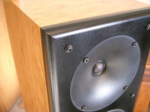
This speaker is fairly typical of a modern waveguide design. It's from Zaph's site here : Zaph|Audio
In a design like this, there are basically three "ranges"
1) In the top octave, about 10khz to 20khz, directivity is solely determined by the tweeter diaphragm. The geometry of the tweeter determines the directivity. Nothing else. The tweeter doesn't "see" the waveguide.
2) In the bottom octave, about 2.5khz to 5khz, the wavelengths are constrained by the waveguide. 5khz is 6.8cm long, so it's large enough that it's directivity is constrained by the waveguide.
3) So the 'trick' is that octave in between the top and the bottom. There's a lot of different options here. You could use an OS waveguide and sacrifice low frequency loading, you could use a diffraction slot to try and have your cake and eat it too, you could vary the beamwidth of the waveguide, etc. You can see this in Zaph's measurements; the wavefront only "sees" the waveguide below 5khz, hence the 'lift' in output.
Last edited:
- Status
- This old topic is closed. If you want to reopen this topic, contact a moderator using the "Report Post" button.
- Home
- Loudspeakers
- Multi-Way
- ABEC experts - help!