@EarlK, wouldn't an estimate be sufficient?
Allen, I am currently working with estimates ( for the offset ) using anywhere from 1.5" to 2.5" (with the woofers acoustic center set behind that of the tweeter ) .
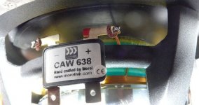
A few of my mock-ups use 2" as the default offset ( which IME does seem like a lot for such tiny drivers > though the included closeup of the driver offers maybe a different perspective ).
Given Niklas's ( youngish ) age, I'm trying to keep the electrical crossover point right around the 2K mark ( so that he can contemplate having these components for a long long time ) .
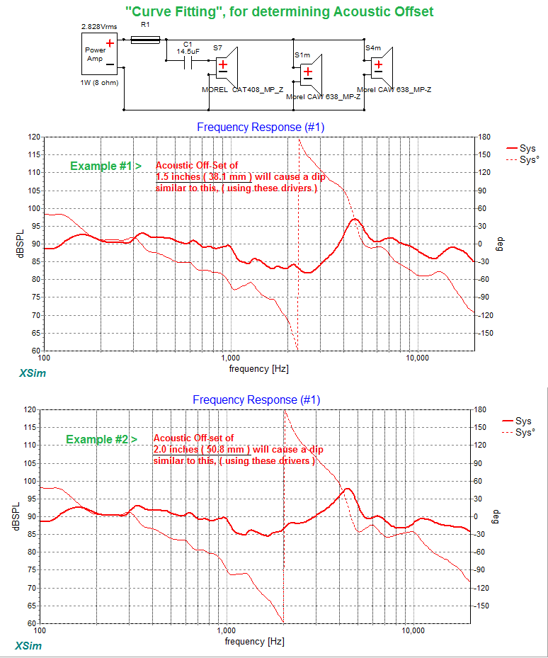
I have already done some "curve-fitting" to roughly guesstimate an offset .
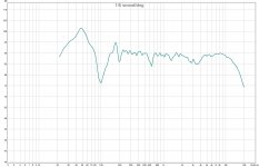
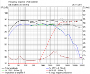
Here's an FR that belongs to Niklas ( taken from his blog ) that shows his twin subs added to the Morel MTMs .
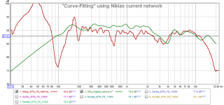
Specifically, I hope ( for my own edification ) to get to the bottom of some of the discrepancies seen in the following pic.
One can see there is good general agreement in the shape of the 2K to 4.5K notch ( but not so much, the notch depth ).
- The real problem here is, the displayed notch ( of my working files ) has something like a 4K bottom while in real life, the bottom of the notch ( from Niklas's actual measurements ) is @ 3500hz.
- If I add distance to the woofers offset to get my notch to move over to 3500 hz, then the general shape really goes to hell ( which then leads me to believe I have some errors baked into my files ) .
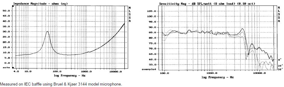
All my FR & ZMA files were created using tracing software ( of Morels own cut-sheets ).
The .Frd files were put through Blender ( to add 12db hipass & lowpass tails ) before Minimum Phase files were extracted ( for my use within XSim ).
")
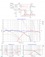
PS; Here's a teaser for Niklas ( this is a few days old using a shallower offset > and is not a finished design )
Attachments
Last edited:
Thank you very much!
I'm up for it, I just don't know how to start. I'm away for work this weekend but I'm free the whole coming week so I'll have plenty of time for measurements.
Not to worry Niklas, when you're done with your shifts at the plant, I'll give you some guidance on making the measurements that I need .
EarlK, I'm delighted you're having a serious go at "the speaker from hell", AKA the 6" bass. Especially since Lojzek has deserted us for his Peerless PPB 830874 project.
I do hate this one. I never get it sounding quite how I like, and it always seems to force me to a lower crossover than I really like.
I'd take a chance and go for 2" or 5cms acoustic offset here. I have seen some evidence that lively cone material brings the acoustic centre forward, but here we at the damped end with polycone Morel.
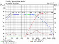
I took your idea and ran with it. 1.8mH and 6.8uF per driver is a regular sort of solution with a lot of 8 ohm drivers. I thought that rather than 0.9mH and 13uF, 1mH and 12uF is going to be very similar and easier to get hold of.
My modelling is with different drivers, but gives a qualitative taste of what a 5kHz notch (if in doubt, notch higher and shallower...) might do to that troublesome 4.5kHz bump. You can do it two ways, can't you? Because it takes down the midrange a little, the tweeter might need taming a little too. Phase alignment improves for sure. Here's what I got for some second order solutions. But you crack on!
I think your modelling will be far better and more specific than mine.
I do hate this one. I never get it sounding quite how I like, and it always seems to force me to a lower crossover than I really like.
I'd take a chance and go for 2" or 5cms acoustic offset here. I have seen some evidence that lively cone material brings the acoustic centre forward, but here we at the damped end with polycone Morel.
I took your idea and ran with it. 1.8mH and 6.8uF per driver is a regular sort of solution with a lot of 8 ohm drivers. I thought that rather than 0.9mH and 13uF, 1mH and 12uF is going to be very similar and easier to get hold of.
My modelling is with different drivers, but gives a qualitative taste of what a 5kHz notch (if in doubt, notch higher and shallower...) might do to that troublesome 4.5kHz bump. You can do it two ways, can't you? Because it takes down the midrange a little, the tweeter might need taming a little too. Phase alignment improves for sure. Here's what I got for some second order solutions. But you crack on!
I think your modelling will be far better and more specific than mine.
Attachments
Last edited:
Thanks for the encouragement Steve ( and thanks for the link to the older backgrounding thread > I likely wouldn't have participated here if I hadn't read it ).
I'm hoping to learn a few things out of this exercise ( such as the pitfalls of creating and using Minimum Phase files from what are essentially 2D file sources ).
Early on I had tried a 4.5K notch ( though I only tried a series type across the driver with no impedance correction > anyways, it didn't work very well > actually, not at all ).
The parallel notch has worked much better & seems to be an option that Niklas might employ ( or not ) as his discretion .
- My added notch takes 4.5Khz down a good 10db, getting 4.5Khz close to 20db below the pass-band ( a figure that's somewhat an arbitrary & personal threshhold when looking to hide nastiness below the fundamental ).
which then leads me to believe I have some errors baked into my files
Impedance and electrical response of your teaser crossover are different from what I get. Is there possibly no valid phase data in your zma files?
Attachments
Hi Niklas,
I'll put together a small guide for you and then post it by end of today, ( today = my day, on this side of the atlantic ).
- Then you can start making some measurements.
Also, do you own any other large ( non-polarized caps ) 20uF, or larger ?
- ( it'll be useful as a dc blocking cap when doing the offset tests > though it's use isn't critical > it's more for safety purposes )
Hi Niklas,
I'll put together a small guide for you and then post it by end of today, ( today = my day, on this side of the atlantic ).
- Then you can start making some measurements.
Also, do you own any other large ( non-polarized caps ) 20uF, or larger ?
- ( it'll be useful as a dc blocking cap when doing the offset tests > though it's use isn't critical > it's more for safety purposes )
Excellent, thank you!
No, have no other filter components, only a MiniDSP if it is of any help.
Hi Niklas,
So, moving forward.
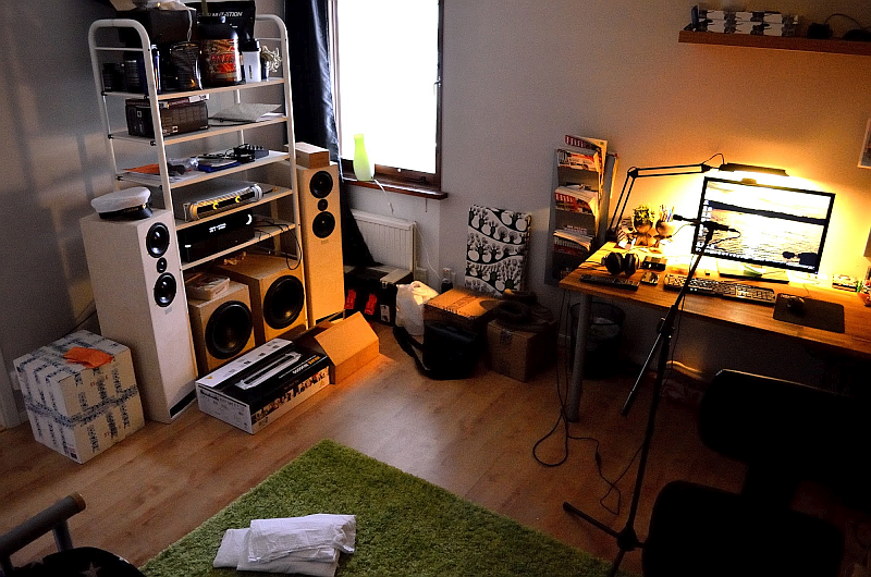
Here's an older pic of your setup;
SPEAKER Preparations :
(1) Remove both crossovers from the speakers ( we need all 4 capacitors to obtain a largish value, and we certainly don't want those inductors involved here ).
(2) Make sure the woofer wires are paralleled together ( and are marked as such ) and hanging out the bottom port ( extend if necessary with some 2-conductor wire ). Clearly mark on the wires which wire is connected to the positive terminal of the woofers .
(3) Do exactly the same for the tweeter
(4) Wire together ( Parallel ) all 4 of your existing caps and attach one end to the wire that's connected to the positive terminal of the tweeter.
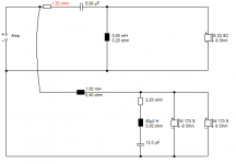
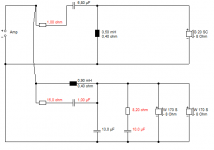
The following diagram shows the wiring configuration ( that we'll be using ) for the 3 drivers being measured. ( Forget about R1, for our purpose here, it doesn't exist ).
Wire your 2 sets of speaker leads together ( woofers & tweeter in parallel ) taking care that the woofer signal is derived from before the 4 inline capacitors ) .

MEASUREMENT Location & Orientation ( within your room )
(1)If you still have that nice ( cube like ) white cardboard box ( to the left of the left-most speaker ) , place it within corner of that green carpet ( assuming the box will hold the weight of 1 speaker, if not, use a stool ) .
(2) Place the speaker ( previously ) prepared for testing on top of the box facing at the camera ( that took this pic ) .
(3) Shuffle about both pieces ( speaker & box-plinth ) a bit so that they are a good meter away from any hard objects ( to their immediate left or right ) .
(4) Point your test mic on-axis ( not 90deg pointed upwards ), centered on the tweeter, from 1 meter away.
- Distance from center of each woofer's dustcap, to the tip of the test mic should be the same distance.
- FWIW, make sure you load the 0deg calibration file into REW.
- Make sure that there's a good meter to meter & 1/2 of space behind the mic ( to minimize reflections )
(5) Connect a test amp to the speaker, then connect your computer ( that runs REW ) to the amp ( either directly or through a pre-amp of sorts ).
(6) Open up REW and power up the amp and run some REW pink noise into the system. See if you can with-stand a 90db level ( it's pretty loud, so 80db is also acceptable ).
MEASUREMENTS Needed :
****NOTE**** Don't move the mic ( or speaker ) in between measurements.
(1) Tweeter and woofer together ( as per the wiring diagram above )
(2) Tweeter only ( with the 4 capacitors still inline )
(3) Woofers only ( but still paralleled together as a working pair )
MEASUREMENTS Delivery :
Zip the .mdat file and upload it here within a post.
- If you can't do that, let me know & I'll PM you my email address.
So, moving forward.
Here's an older pic of your setup;
SPEAKER Preparations :
(1) Remove both crossovers from the speakers ( we need all 4 capacitors to obtain a largish value, and we certainly don't want those inductors involved here ).
(2) Make sure the woofer wires are paralleled together ( and are marked as such ) and hanging out the bottom port ( extend if necessary with some 2-conductor wire ). Clearly mark on the wires which wire is connected to the positive terminal of the woofers .
(3) Do exactly the same for the tweeter
(4) Wire together ( Parallel ) all 4 of your existing caps and attach one end to the wire that's connected to the positive terminal of the tweeter.
The following diagram shows the wiring configuration ( that we'll be using ) for the 3 drivers being measured. ( Forget about R1, for our purpose here, it doesn't exist ).
Wire your 2 sets of speaker leads together ( woofers & tweeter in parallel ) taking care that the woofer signal is derived from before the 4 inline capacitors ) .
MEASUREMENT Location & Orientation ( within your room )
(1)If you still have that nice ( cube like ) white cardboard box ( to the left of the left-most speaker ) , place it within corner of that green carpet ( assuming the box will hold the weight of 1 speaker, if not, use a stool ) .
(2) Place the speaker ( previously ) prepared for testing on top of the box facing at the camera ( that took this pic ) .
(3) Shuffle about both pieces ( speaker & box-plinth ) a bit so that they are a good meter away from any hard objects ( to their immediate left or right ) .
(4) Point your test mic on-axis ( not 90deg pointed upwards ), centered on the tweeter, from 1 meter away.
- Distance from center of each woofer's dustcap, to the tip of the test mic should be the same distance.
- FWIW, make sure you load the 0deg calibration file into REW.
- Make sure that there's a good meter to meter & 1/2 of space behind the mic ( to minimize reflections )
(5) Connect a test amp to the speaker, then connect your computer ( that runs REW ) to the amp ( either directly or through a pre-amp of sorts ).
(6) Open up REW and power up the amp and run some REW pink noise into the system. See if you can with-stand a 90db level ( it's pretty loud, so 80db is also acceptable ).
MEASUREMENTS Needed :
****NOTE**** Don't move the mic ( or speaker ) in between measurements.
(1) Tweeter and woofer together ( as per the wiring diagram above )
(2) Tweeter only ( with the 4 capacitors still inline )
(3) Woofers only ( but still paralleled together as a working pair )
MEASUREMENTS Delivery :
Zip the .mdat file and upload it here within a post.
- If you can't do that, let me know & I'll PM you my email address.
Attachments


Last edited:
Hi Niklas,
So, moving forward.
Here's an older pic of your setup;
SPEAKER Preparations :
(1) Remove both crossovers from the speakers ( we need all 4 capacitors to obtain a largish value, and we certainly don't want those inductors involved here ).
(2) Make sure the woofer wires are paralleled together ( and are marked as such ) and hanging out the bottom port ( extend if necessary with some 2-conductor wire ). Clearly mark on the wires which wire is connected to the positive terminal of the woofers .
(3) Do exactly the same for the tweeter
(4) Wire together ( Parallel ) all 4 of your existing caps and attach one end to the wire that's connected to the positive terminal of the tweeter.
The following diagram shows the wiring configuration ( that we'll be using ) for the 3 drivers being measured. ( Forget about R1, for our purpose here, it doesn't exist ).
Wire your 2 sets of speaker leads together ( woofers & tweeter in parallel ) taking care that the woofer signal is derived from before the 4 inline capacitors ) .
MEASUREMENT Location & Orientation ( within your room )
(1)If you still have that nice ( cube like ) white cardboard box ( to the left of the left-most speaker ) , place it within corner of that green carpet ( assuming the box will hold the weight of 1 speaker, if not, use a stool ) .
(2) Place the speaker ( previously ) prepared for testing on top of the box facing at the camera ( that took this pic ) .
(3) Shuffle about both pieces ( speaker & box-plinth ) a bit so that they are a good meter away from any hard objects ( to their immediate left or right ) .
(4) Point your test mic on-axis ( not 90deg pointed upwards ), centered on the tweeter, from 1 meter away.
- Distance from center of each woofer's dustcap, to the tip of the test mic should be the same distance.
- FWIW, make sure you load the 0deg calibration file into REW.
- Make sure that there's a good meter to meter & 1/2 of space behind the mic ( to minimize reflections )
(5) Connect a test amp to the speaker, then connect your computer ( that runs REW ) to the amp ( either directly or through a pre-amp of sorts ).
(6) Open up REW and power up the amp and run some REW pink noise into the system. See if you can with-stand a 90db level ( it's pretty loud, so 80db is also acceptable ).
MEASUREMENTS Needed :
****NOTE**** Don't move the mic ( or speaker ) in between measurements.
(1) Tweeter and woofer together ( as per the wiring diagram above )
(2) Tweeter only ( with the 4 capacitors still inline )
(3) Woofers only ( but still paralleled together as a working pair )
MEASUREMENTS Delivery :
Zip the .mdat file and upload it here within a post.
- If you can't do that, let me know & I'll PM you my email address.
Thank you very much for that detailed instruction! I moved out of that house over four years ago and have moved several times since then. Here is what my current listening room looks like.


It sounds like this measurement will take at least a couple of hours to perform, and I am not sure I will have enough time tomorrow. But I will start fabricating cables to use and figure out a way to use the caps. They are glued to the filter board so I don't think I can remove them in any easy way. If I want to use them in the new filter I will have to cut/grind away the plywood from them I think.
Hi Niklas,
Yes, your current capacitors will be usable in any future crossover ( so don't break the leads off them ).
( Alternately ), can you buy anywhere ( locally ) 15uF to 20 uF caps ( or do you have to order online to your city/town ) ?
- It would actually be helpful if these HiPass caps were really large ( such as 30 to 40uF )
Those larger values will be used ( no matter what ) within the woofer portion of a new network.
- Non-polarized electrolytics are fine ( if available ) and really cheap ( and can be bypassed by small value MP caps to improve their performance ).
Motor Run MPP's would be my first ( economical & good-sounding ) choice .
( MPP = Metalized Polypropylene )
The new digs do look more spacious ! That'll help get cleaner captures with REW .
Hi Niklas,
Yes, your current capacitors will be usable in any future crossover ( so don't break the leads off them ).
( Alternately ), can you buy anywhere ( locally ) 15uF to 20 uF caps ( or do you have to order online to your city/town ) ?
- It would actually be helpful if these HiPass caps were really large ( such as 30 to 40uF )
Those larger values will be used ( no matter what ) within the woofer portion of a new network.
- Non-polarized electrolytics are fine ( if available ) and really cheap ( and can be bypassed by small value MP caps to improve their performance ).
Motor Run MPP's would be my first ( economical & good-sounding ) choice .
( MPP = Metalized Polypropylene )
The new digs do look more spacious ! That'll help get cleaner captures with REW .
I know, they are expensive parts and I wouldn't risk any permanent damage to them.
These are the only capacitors I can get locally Luxorparts Kondensatorsortiment elektrolyt 120-pack - Komponentsatser | Kjell.com
I live in a smallish (50k pop) town in northern Sweden so there's not much to chose from, unfortunately. I could order online but that would me I probably wouldn't get them before the weekend. However it would probably cost me about the same as the pack above and I would have a lot more to chose from. This website Kop Kondensatorer stort urval @ Electrokit has cheap shipping (29SEK or around $3.50) and should have what I need.
Edit: Actually, buying from that site could save me a lot of money. If I don't have to use my current capacitors I could skip alligator clips and save money that way and just buy some cheap throwaway capacitors and solder instead. Would something like this be sufficient? Kop El.lyt 47uF 100V axiell 10x25 till ratt pris @ Electrokit
Last edited:
No, ( those in the last link won't do, because they're polarized electrolytics ).
- ( semantics-wise: "non-polar" = bi-polar )
Buy a pair of low-voltage, non-polarized 20uF electrolytics ( and then parallel them together to get 40uF ).
- This is the most "disposable option" for you.
Alternately, buy a pair of Motor-Run caps ( for future use in the new network ) from this page at that site.
- 16uF to 20uF will be the most useful for inclusion into a future network ( assuming the acoustic offset is 50mm or more )
PS: I'm not in any hurry here, 99% of my work is already done ( there's just a bit of parts-value tweaking to do ) / so don't rush things on my account if you want to ponder your options.
- leaving your current networks intact during the testing ( & acquisition ) phases will mean you don't go without tunes for very long .
Last edited:
No, ( those in the last link won't do, because they're polarized electrolytics ).
- ( semantics-wise: "non-polar" = bi-polar )
Buy a pair of low-voltage, non-polarized 20uF electrolytics ( and then parallel them together to get 40uF ).
- This is the most "disposable option" for you.
Alternately, buy a pair of Motor-Run caps ( for future use in the new network ) from this page at that site.
- 16uF to 20uF will be the most useful for inclusion into a future network ( assuming the acoustic offset is 50mm or more )
PS: I'm not in any hurry here, 99% of my work is already done ( there's just a bit of parts-value tweaking to do ) / so don't rush things on my account if you want to ponder your options.
- leaving your current networks intact during the testing ( & acquisition ) phases will mean you don't go without tunes for very long .
Oh, okay.
Those motor-run caps cost about the same as Mundorf M-Cap from Supersonic Svenska AB - Ljudanläggningar & Talat utrymningslarm - supersonic (although shipping is a lot more expensive there). A set of 2x16uF + 2x20uF motor-run caps from Electrokit will cost 475SEK and a set of 2x15uF + 2x22uF Mundorf E-Cap Plain would cost me 225SEK, so less than half the price. A set of 15+22uF 250V Mundorf M-Cap would cost me 456SEK including shipping, so I guess the Mundorf are a better option than the motor-run caps.
I am not in a hurry either. I've been using the old crossovers for several years now and they work fine. I'd rather let this take a couple of weeks extra and be sure I get it right and don't waste too much money in the process.
(A) For clarity, you would only need to buy 2 caps from Electrokit ( not 4 if that was what you think I meant ).
- ie; 2 x 16uF or 2 x 20uF .
(B) Alternately, one can make a working BiPolar cap ( at least for our test purposes ) from 2 non-polar electrolytics, by series ( or parallel ) wiring them together with the + terminals at opposite ends to each other.
- Depending on the configuration type , one either adds the values directly ( parallel ) or halves the value of one cap ( if the caps are equal value and in series with each other ) .
You're right, I had a brain fart there.
This makes Mundorf M-Cap around 30SEK more expensive (practically nothing) and I guess they are the better choice if I want to use them later in the final design?
The final network design will most likely call for cap values that don't equate to either 15uF or 22uF.
In this case 15uF is a safer value to own ( for future use ).
- One can always top-up it's value by adding more capacitance in parallel.
Buy a few 5 watt resistors while your at it. That shouldn't alter your shipping costs.
>> buy; 2 x 1R plus 2 x 1.5R ( 10% tolerance should do )
In this case 15uF is a safer value to own ( for future use ).
- One can always top-up it's value by adding more capacitance in parallel.
Buy a few 5 watt resistors while your at it. That shouldn't alter your shipping costs.
>> buy; 2 x 1R plus 2 x 1.5R ( 10% tolerance should do )
The final network design will most likely call for cap values that don't equate to either 15uF or 22uF.
In this case 15uF is a safer value to own ( for future use ).
- One can always top-up it's value by adding more capacitance in parallel.
Buy a few 5 watt resistors while your at it. That shouldn't alter your shipping costs.
>> buy; 2 x 1R plus 2 x 1.5R ( 10% tolerance should do )
Okay, in that case I'll stick to the cheaper Mundorf E-Cap Plain and save some money.
So, 15uF, 22uF, 2x1R, 2x1.5R. Is there anything else I should add?
- Status
- This old topic is closed. If you want to reopen this topic, contact a moderator using the "Report Post" button.
- Home
- Loudspeakers
- Multi-Way
- New crossover for my current speakers