Something like that. Here is a rough idea of how to go about it. Its harder to describe than to do, given some familiarity with a 3D CAD tool.
Draw a square on the surface of the horn a short distance in from the apex. Now draw an arc that is tangent to the CD's exit cone at one end and tangent to the horn wall at the midpoint of one side of the square at the other end. (This is the hard part, you may need to re-position the square or the horn wall to satisfy both constraints.)
Once you have that arc, rotate it around the circle defining the CD exit to create a 3D surface. (In SketchUp, use the follow me tool.)
Now the 3D surface touches the square you drew at just 4 points. Draw additional lines to fill in the corners smoothly emulating the process with modelling clay I described earlier.
Ultimately you will define a surface and underlying structure to be milled or printed but you still have to decide how to integrate it with the horn. Lots to keep you busy until after Christmas.
MR. Oil,
If you use Fusion 360 to make your 3D printed designs, you can import tables of numbers into it. With a spreadsheet, you can use the Oblate Spheroid formulas to generate the needed tables. See attached Excel file for one I used -- but, sorry, can't answer many questions about it, as I don't remember well what I was doing then, and didn't keep notes!. But I used a radius for the last third or so of the curve and tweaked values to get the curves to meet.

Then export the table (trim it down to maybe 15 or so values, with most detail at the throat end) as a csv file. Fusion 360 can import the table(s) as spline curves (it smooths out between the provided points), and with those you can rotate them for a round horn shape; or use them as "guides" for lofting between a circle and whatever mouth (or adaptor) shape you are looking for for non-round shapes.
If you use Fusion 360 to make your 3D printed designs, you can import tables of numbers into it. With a spreadsheet, you can use the Oblate Spheroid formulas to generate the needed tables. See attached Excel file for one I used -- but, sorry, can't answer many questions about it, as I don't remember well what I was doing then, and didn't keep notes!. But I used a radius for the last third or so of the curve and tweaked values to get the curves to meet.
Then export the table (trim it down to maybe 15 or so values, with most detail at the throat end) as a csv file. Fusion 360 can import the table(s) as spline curves (it smooths out between the provided points), and with those you can rotate them for a round horn shape; or use them as "guides" for lofting between a circle and whatever mouth (or adaptor) shape you are looking for for non-round shapes.
Attachments
Last edited:
Thanks for taking the time...Something like that. Here is a rough idea of how to go about it. Its harder to describe than to do, given some familiarity with a 3D CAD tool.<snip>
I can't understand what you are saying (not my mother tongue), but I have an idea on how this thing could look like... (atached)
Is this correct?
Greetings
Attachments

Its a start. What you have there, with a few more lines added, could do the round to rectangular conversion. Just draw lines from each junction of the polygon that approximates the circle down to the nearest corner of the square. This will do the corner fill. (But it doesn't do the CD exit angle matching.) I actually got a 3D print of such a structure once but never used it in a project because by that time I had something working with modelling clay.
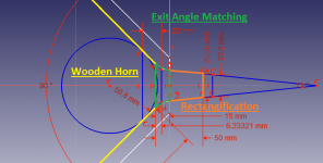
here is what I came up with for the 3d printing or milling:

It matches a 14 degree exit angle and does round to square for a 60x60 horn. I plan to CNC mill it into two layers of 18 mm BB plywood plus .25" of CD mounting plate.
The front part of in, grey, is the corner fill for the round to rectangular converstion. The back part is the exit angle matching for a BMS4550.
BWaslo and I were talking about how to generate that curve. He from a x-Y table that approximates an ideal Oblate Spheroidic expansion, me from simpler criterion. Once you have such a curve, you can use Sketchup's "follow-me" tool to move it around a circle to create the needed expanding pipe, which you then edit into your horn drawing. That expanding pipe is what you see in the back half of my drawing above.
I got my curve graphically by starting with the Charles Hughes whitepaper on quadratic throat waveguide and then added the exit angle matching criterion to it. There is a figure (see below) in the white paper which should get you started. I hesitate to say more if there is a language barrier between us. You really need to work your way through the process yourself as there are several of design decisions you need to make along the way.

here is what I came up with for the 3d printing or milling:
It matches a 14 degree exit angle and does round to square for a 60x60 horn. I plan to CNC mill it into two layers of 18 mm BB plywood plus .25" of CD mounting plate.
The front part of in, grey, is the corner fill for the round to rectangular converstion. The back part is the exit angle matching for a BMS4550.
BWaslo and I were talking about how to generate that curve. He from a x-Y table that approximates an ideal Oblate Spheroidic expansion, me from simpler criterion. Once you have such a curve, you can use Sketchup's "follow-me" tool to move it around a circle to create the needed expanding pipe, which you then edit into your horn drawing. That expanding pipe is what you see in the back half of my drawing above.
I got my curve graphically by starting with the Charles Hughes whitepaper on quadratic throat waveguide and then added the exit angle matching criterion to it. There is a figure (see below) in the white paper which should get you started. I hesitate to say more if there is a language barrier between us. You really need to work your way through the process yourself as there are several of design decisions you need to make along the way.
If you use Fusion 360 to make your 3D printed designs, you can import tables of numbers into it.
Nice, thanks! I've been wondering if this was possible but never knew how. I just found this quick tutorial for anyone else interested: Importing XYZ data from Excel into Fusion 360 | Fusion 360 | Autodesk Knowledge Network
Hi,
Back working at this after a busy week...
@nc535 I was wondering if the exit angle matching needs to be a curve... (can't see it on the 1st pic)
In the case of the 2nd picture the exit angle would be 0°, right?
Also how would you implement such a curve in Hornresp?
Thanks for your help!
Back working at this after a busy week...
@nc535 I was wondering if the exit angle matching needs to be a curve... (can't see it on the 1st pic)
In the case of the 2nd picture the exit angle would be 0°, right?
Also how would you implement such a curve in Hornresp?
Thanks for your help!
Yes, the exit angle matching requires a curve; otherwise its simply an extension of the straight conic section (assumed to be) inside the CD and there will still be an abrupt change of slope that will cause diffraction and reflection where the line meets the horn.
Right, the picture from the Charles Hughes white paper is for a 0 degree exit angle. It would be more accurate to say they weren't addressing the need for exit angle matching.
That curved throat section can't be modeled in HR. HR gives you choice of conical, parabolic, and exponential for each segment of the horn and some ability to model a throat chamber but that isn't sufficient. Most likely you would need to model both the CD and the waveguide in something like ABEC3 to see the beneficial effect.
Nice, thanks! I've been wondering if this was possible but never knew how. I just found this quick tutorial for anyone else interested: Importing XYZ data from Excel into Fusion 360 | Fusion 360 | Autodesk Knowledge Network
Hi Nate:
I googled "Importing XYZ data from Excel into Sketchup" and found this link
Importing geometry from Excel or text files - Ruby API - SketchUp Community
Now that I know its possible in Sketchup also, I guess I'll have to try it. Thanks for the push, even though its sure to make my brain hurt
")
Jack
Jack - thanks for the link. Now if I can figure out how to create points along an arbitrary spline for export to AxiDriver I will be in business.
To keep this ot MrOIL - I wouldn't worry much about simming the throat of the wg for the hf portion on your Synergy. To be honest I've never paid it much attention, only using it to figure out midrange ports which are going to be unaffected by a radius at the cd entrance or not. That radius will create a change of distance but I would think for our purposes it would be negligible.
To keep this ot MrOIL - I wouldn't worry much about simming the throat of the wg for the hf portion on your Synergy. To be honest I've never paid it much attention, only using it to figure out midrange ports which are going to be unaffected by a radius at the cd entrance or not. That radius will create a change of distance but I would think for our purposes it would be negligible.
I worked a bit here and there and I think that I'm finished now...
I had a little problem regarding the throat adapter; I now have the round to square adapter before the exit angle matching, because I use an asymmetric dispersion (60*90).
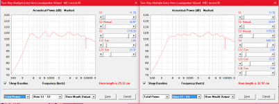
When i was finished i just wanted to try to remove the expansion change in the horn and the results were almost the same (see pics).
Should I remove the expansion change?
Are there any errors I made and what do you think of the results?
The dip around 11kHz is from the mid ports acting as a helmholtz resonator I would suspect. Is this correct?
Thanks in advance!
I had a little problem regarding the throat adapter; I now have the round to square adapter before the exit angle matching, because I use an asymmetric dispersion (60*90).
When i was finished i just wanted to try to remove the expansion change in the horn and the results were almost the same (see pics).
Should I remove the expansion change?
Are there any errors I made and what do you think of the results?
The dip around 11kHz is from the mid ports acting as a helmholtz resonator I would suspect. Is this correct?
Thanks in advance!
Attachments
I worked a bit here and there and I think that I'm finished now...<snip>
The secondary expansion is reducing the frequency response ripple in the lower midrange and has other benefits not visible in the power response graph. This ripple, I believe, is caused by reflections due to impedance mismatch at the mouth. The secondary flare reduces these mouth reflections, roundovers would reduce them further.
The secondary flare also reduces waistbanding which is a widening of the directivity about an octave above where the horn loses pattern control.
If you modify your model without the secondary flare to make it an ND horn with a single flare instead of an OD driven from S2, you will be able to run directivity plots and the waistbanding will be evident in them.
HR will do directivity only for single segment horns so you won't be able to simulate the improvement in directivity of the secondary flare but it is well proven in practice.
The one thing I would question is the sequence in which you have done have done the round to rectangular conversion and then exit angle matching. Ask yourself if by extending the angle of the CD into the horn you have made the reflection distance (mid port to CD diaphragm) longer than it would otherwise need to be.
I think that you have and that this might get in the way of extending the mid's response high enough. In your drawing at least you don't achieve straight/flat horn walls until after the exit angle matching and this can't help but push your mids further away from the apex.
Its more conventional to do the exit angle matching first - closest to the CD. Start it in the CD mounting plate and continue it into the horn. At some point your gradually transition from round aperture to elliptical and then fill in the corners to finish off the round to rectangular conversion.
Doing this on a square horn is easier - you just go round to square instead of round to elliptical to rectangular.
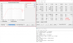
I've shortened the adapter to 3cm and changed the mid port size.
I got 3 questions left:
1. Do I need to worry about delays?
2. What causes the two dips over 10kHz? Should I worry about them?
3. Is the Mid compression ratio really ok? I've seen some pictures with the exact same driver that took damage on the opposite site of the ports:

(from: TH & Unity Horn 24v wind & solar system - Speakerplans.com Forums - Page 5)
Thanks a lot!
I got 3 questions left:
1. Do I need to worry about delays?
2. What causes the two dips over 10kHz? Should I worry about them?
3. Is the Mid compression ratio really ok? I've seen some pictures with the exact same driver that took damage on the opposite site of the ports:
(from: TH & Unity Horn 24v wind & solar system - Speakerplans.com Forums - Page 5)
Thanks a lot!
Attachments
Delays are nothing to worry about if you are going with an active crossover; just dial in the delay that you need to achieve time alignment. If going passive, its another story and quite challenging to get linear phase.
I wouldn't worry about those dips given the limits of the CD modelling that can be done in HR. I have no doubt though that when you build the horn you will need to do some equalization of the HF, another argument for active XO.
Damage to mid surrounds usually comes from the surround hitting the horn wall at full excursion, as was the case in the thread you linked. You should space away or route a channel to clear at Xmech, not Xmax. Its better to route into the horn wall because spacing the driver away from the horn wall increases the Vtc. Changing the spacing will also vary the delay.
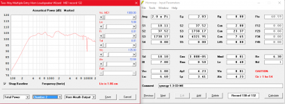
Instead of worrying about compression ratio, check the particle velocity in the mids' throat port exit using HR. If its less than about 17 m/s at peak, like a bass reflex port, then its OK.
I wouldn't worry about those dips given the limits of the CD modelling that can be done in HR. I have no doubt though that when you build the horn you will need to do some equalization of the HF, another argument for active XO.
Damage to mid surrounds usually comes from the surround hitting the horn wall at full excursion, as was the case in the thread you linked. You should space away or route a channel to clear at Xmech, not Xmax. Its better to route into the horn wall because spacing the driver away from the horn wall increases the Vtc. Changing the spacing will also vary the delay.
Instead of worrying about compression ratio, check the particle velocity in the mids' throat port exit using HR. If its less than about 17 m/s at peak, like a bass reflex port, then its OK.
I adjusted the port to have a max of 16.8m/s velocity. Also I noticed, that the front volume of the driver is more like 50cm^2 (instead of the 120cm^2 I used before), so I think I'll just go with a bigger vtc, as the driver performs better that way... (I will 3d print the expansion.)
Regarding the delay, I wanted to know if I'd be able to ignore the delay, because it would only be around 1.5cm... (I have a Behringer CX2310 crossover and don't want to get a DSP)
I will start building after NYE unless you see any error or anything you would change.
Thanks for your help!
Regarding the delay, I wanted to know if I'd be able to ignore the delay, because it would only be around 1.5cm... (I have a Behringer CX2310 crossover and don't want to get a DSP)
I will start building after NYE unless you see any error or anything you would change.
Thanks for your help!
Attachments
I hate to be the one to tell you but I don't think that Behringer XO is going to do it for you. You are unlikely to get a flat response using just the textbook LR4 filters in the CX2310. You may be able to get away without delays but you will certainly need some PEQs and you may need sharper slopes than LR4.
What filters did you use in the HR MEH simulation?
What filters did you use in the HR MEH simulation?
MrOil, I think even a simple and cheap MiniDSP 2x4 (or better, 2x4HD) would seriously do better than that Behringer for this purpose. An active crossover with DSP is the quickest and easiest way to get a unity-type horn going. If you're going active, why tie your hands by using something that can't adjust delays? All the work and money to make the horn, the cost of a miniDSP is almost insignificant in comparison.
Though, even still, I'd recommend making just one single unity horn to start, and don't try to make it pretty. You'll almost certainly find something you need to or want to change after the first horn (and maybe after the second horn, for that matter). Take the simulations with a "grain of salt" (English expression meaning "assume it's just approximate"). Simulations can be accurate, but no more accurate than the assumptions they are necessarily based on or the data you feed them. For example, those dips you are worrying about won't be like that -- but there will certainly be others that don't show up on the simulation!
(By the way, what parameters are you using for the DE250, how did you get them? I've never found anything).
Last edited:
- Status
- This old topic is closed. If you want to reopen this topic, contact a moderator using the "Report Post" button.
- Home
- Loudspeakers
- Multi-Way
- 2-way Unity Horn from 300Hz (some noob questions)