I’m finally done enough with the printed Unity type waveguide speaker design to post the files. This is a follow on to the thread "3D printing 1/2 of a waveguide". It seemed to make sense to start a new thread, as the first starts out just showing how the waveguide gets printed so it's not obvious there is a design beyond that. I'll post STL files for the printed waveguide, the crossover design, and details on the cabinet construction here. Feel free to comment, discuss, denigrate or even threadjack this.
I sort of doubt that many people will actually build this design even though I think it was a large success. But the build requires many steps in different skills. None of the steps are particularly difficult, but there are a lot of steps!
OK, that's not quite correct. Printing the waveguide is actually a somewhat difficult step, as it requires you to get hold of and configure a large-format 3D printer with a wide 1mm nozzle. Not to mention working through the learning curve of the 3D printer process. I consider myself still as not much beyond a beginner at 3D printing, it's a whole absorbing hobby in itself. You COULD send off the STL files to one of any number of 3D printing houses, though that probably wouldn't be cheap and you'd need to talk to the 3D printing people with specifics about how it needs to be done.
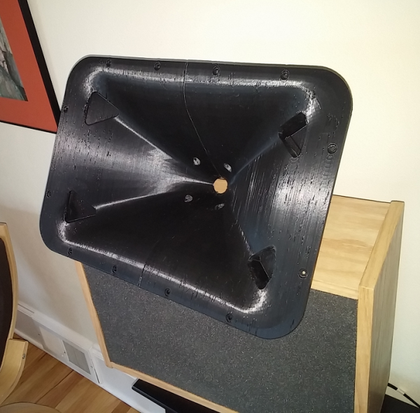
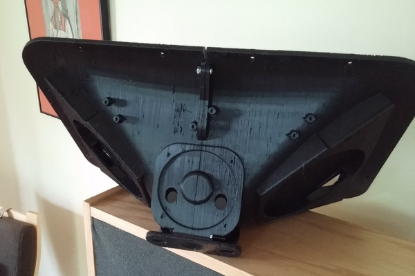
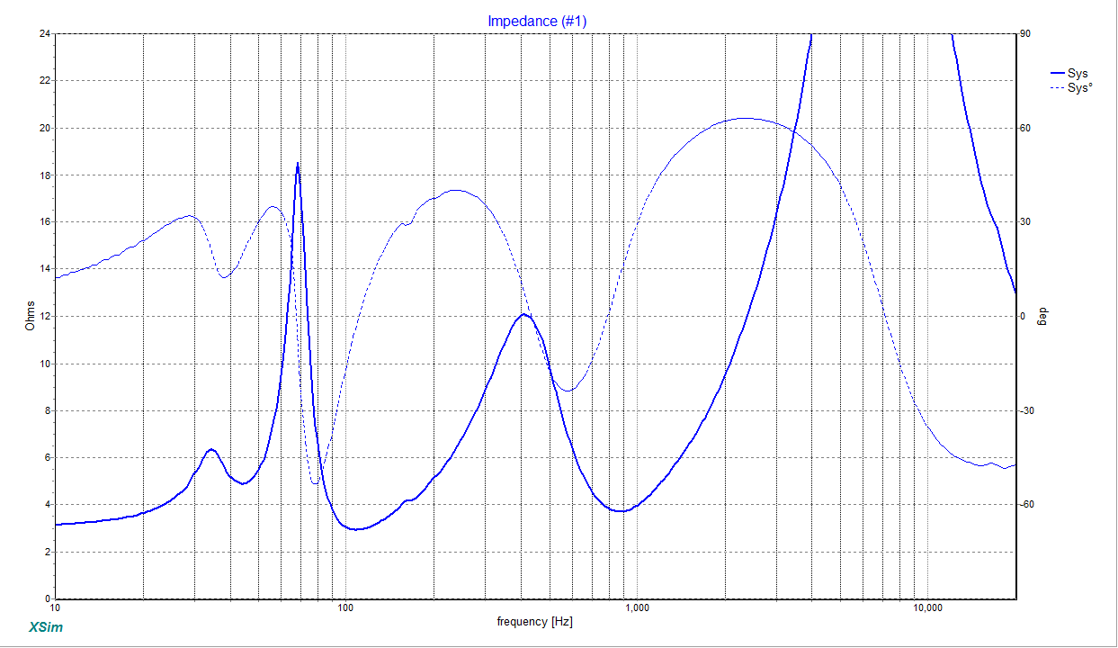
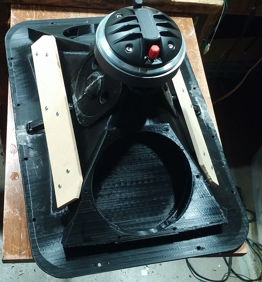
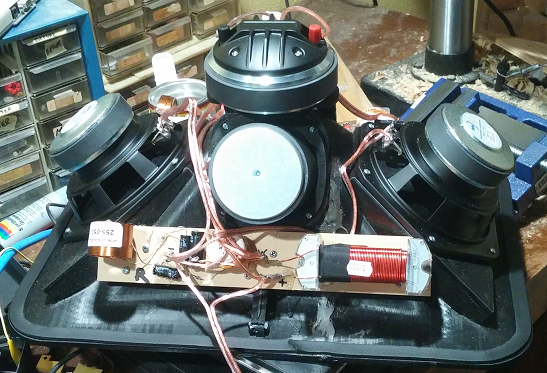
This is what the waveguide looks like after printing, then how it looks with all the drivers and crossover glommed onto it --
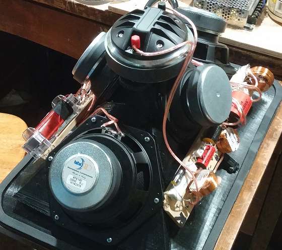
With all that stuff on it, the assembly can be treated like a single drop-in full range speaker driver.
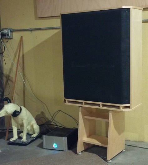
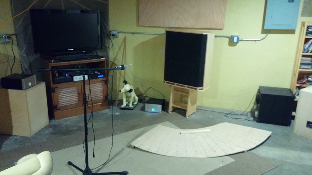
And here is a shot of a completed speaker, sitting on a simple stand I designed for it --
BTW, I had planned to put all these pix in the diyaudio.com gallery, but it no longer accepts new photos so these are being hosted from my own website.
I sort of doubt that many people will actually build this design even though I think it was a large success. But the build requires many steps in different skills. None of the steps are particularly difficult, but there are a lot of steps!
OK, that's not quite correct. Printing the waveguide is actually a somewhat difficult step, as it requires you to get hold of and configure a large-format 3D printer with a wide 1mm nozzle. Not to mention working through the learning curve of the 3D printer process. I consider myself still as not much beyond a beginner at 3D printing, it's a whole absorbing hobby in itself. You COULD send off the STL files to one of any number of 3D printing houses, though that probably wouldn't be cheap and you'd need to talk to the 3D printing people with specifics about how it needs to be done.
This is what the waveguide looks like after printing, then how it looks with all the drivers and crossover glommed onto it --
With all that stuff on it, the assembly can be treated like a single drop-in full range speaker driver.
And here is a shot of a completed speaker, sitting on a simple stand I designed for it --
BTW, I had planned to put all these pix in the diyaudio.com gallery, but it no longer accepts new photos so these are being hosted from my own website.
Last edited:
Here are some measurements. These were unfortunately done in my basement, without enough space to get a completely clean measurement, so some of the irregularities were from reflections off of surfaces and things I couldn’t avoid.
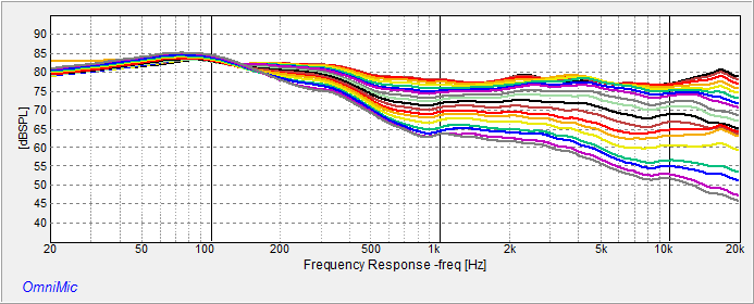
First, a measurement from back at the listening chair (this one is at 1/6h octave smoothing). Bass looks a little overdone, probably some from room effects and some from a perhaps somewhat “plummy” voicing I did in the crossover. Sounds nice though. The midrange and tweeter can be raised quite a bit if desired (I’ll probably reduce the larger bass peak with a DSP equalizer at some point).
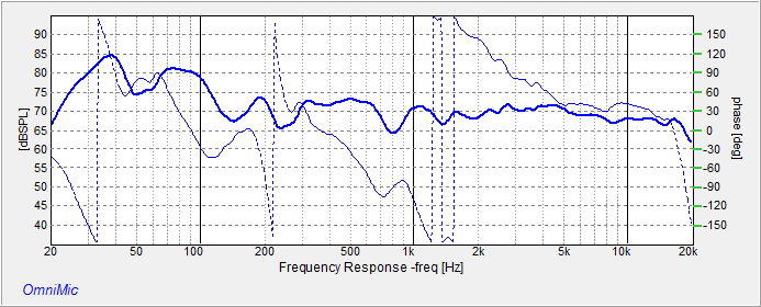
The response below 40Hz is somewhat a mystery to me. The ported design should be dropping sharply below there, but the repeatable measurement shows it somehow boosted there for nearly an octave lower. A friendly room mode?
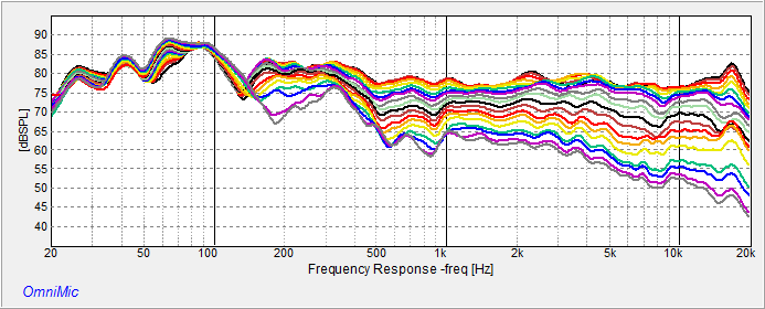
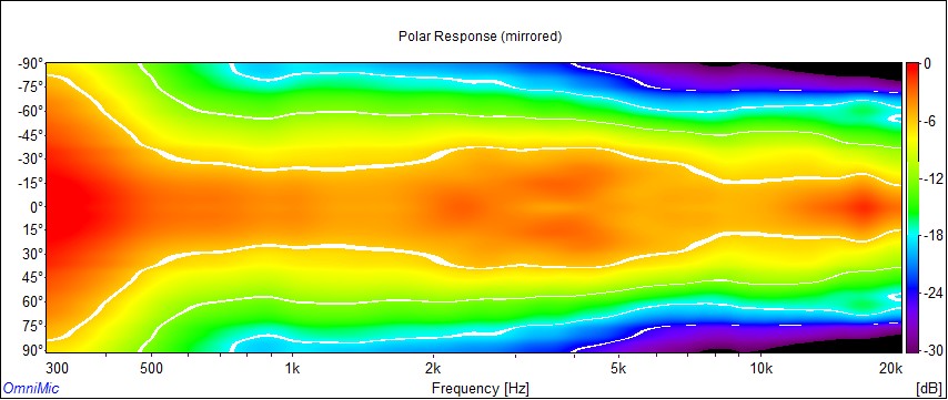
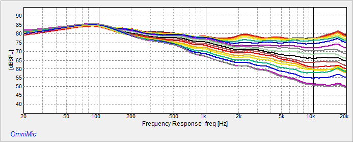
Next, some horizontal measurements at 1m (ignore the SPL levels, they were done low to avoid disturbing others in the house. The measurements should have be done from further away, but I don’t have the space, and doing outdoor testing here is hard to manage.
These are the on-to-off axis frequency response (from 0 to 90 degrees in 5 degree increments), shown with 1/6th octave smoothing and then with “ERB” smoothing (intended to mimic the effects of hearing bandwidths for better indication of the perceived frequency response).
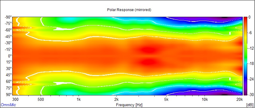
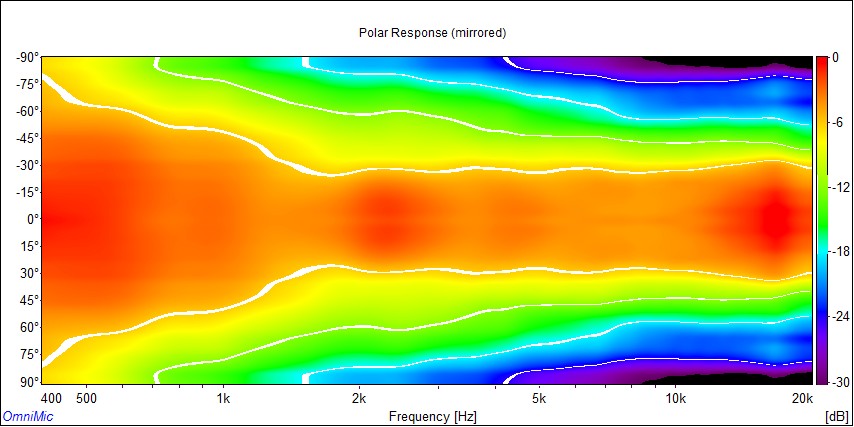
And the same data in “Polar Map” format, first with ERB smoothing and un-normalized, and then ERB and normalized.
Next, vertical curves, 0 to 90 degrees off-axis, 1/6th octave and then ERB:
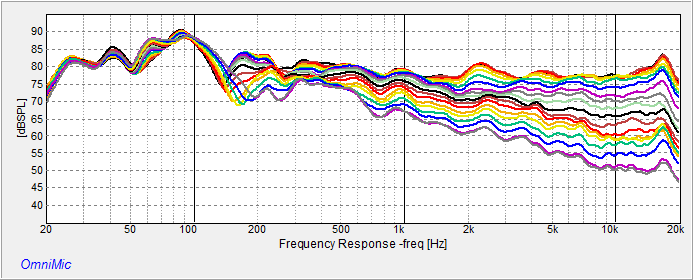
 .
.
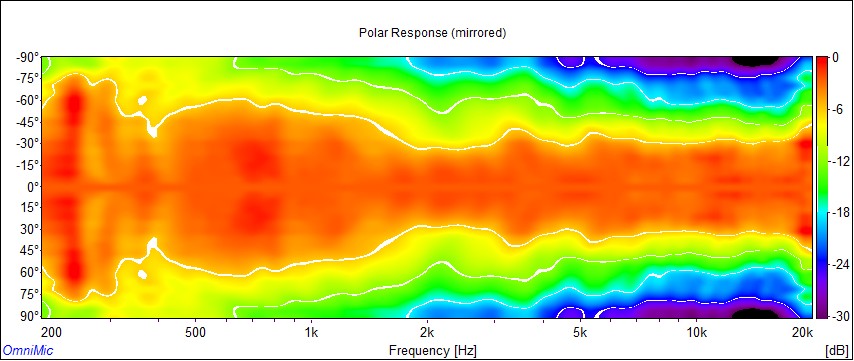
Vertical Polars, ERM un-normalized and normalized:
First, a measurement from back at the listening chair (this one is at 1/6h octave smoothing). Bass looks a little overdone, probably some from room effects and some from a perhaps somewhat “plummy” voicing I did in the crossover. Sounds nice though. The midrange and tweeter can be raised quite a bit if desired (I’ll probably reduce the larger bass peak with a DSP equalizer at some point).
The response below 40Hz is somewhat a mystery to me. The ported design should be dropping sharply below there, but the repeatable measurement shows it somehow boosted there for nearly an octave lower. A friendly room mode?
Next, some horizontal measurements at 1m (ignore the SPL levels, they were done low to avoid disturbing others in the house. The measurements should have be done from further away, but I don’t have the space, and doing outdoor testing here is hard to manage.
These are the on-to-off axis frequency response (from 0 to 90 degrees in 5 degree increments), shown with 1/6th octave smoothing and then with “ERB” smoothing (intended to mimic the effects of hearing bandwidths for better indication of the perceived frequency response).
And the same data in “Polar Map” format, first with ERB smoothing and un-normalized, and then ERB and normalized.
Next, vertical curves, 0 to 90 degrees off-axis, 1/6th octave and then ERB:
Vertical Polars, ERM un-normalized and normalized:
Last edited:
Here’s the STL (the file used to 3D print from) for the waveguide. I designed this to follow the oblate spheroid curves in the center of the horizontal and verticals, and blend from there into a rounded rectangle, ending in a large roundover (somewhat like the SEOS waveguide designs). This file is for one half of a waveguide – two halves get bolted together to form one waveguide. Designed in Fusion 360.
http://libinst.com/SynergyDIY/3DP%20version/DIYAudio/Files/V4%20Waveguide%20for%20DNA360%20TF0410MR%206FE100.stl
Some notes about printing each half-a-waveguide:
1) Print with a 1mm diameter nozzle, for both strength and to make the printing time reasonable (about 12 hours per half). With a standard 0.4mm nozzle, it would take about 3 to 5 DAYS to print a half, so… don’t do that! 3D printing isn’t a fast process. There’s no danger of this design ever being commercially mass manufactured because of that!
2) Print HOT for strength. Expect some flaws on a print that is this big and that is printed with this large coarse nozzle. Keep in mind that the smallest wavelength handled is about ¾ of an inch, so don’t sweat the small millimeter-ish stuff. Weak spots or even cracks can be filled with JBWeld epoxy, and spray painted with a can for cosmetics. Make sure you have files and sandpaper handy.
3) Print densely. With 1mm filament (1.2mm extrusion width), I used three perimeters and 30% infill, which with the waveguide wall thickness results in nearly solid plastic walls. You can make a cosmetically acceptable waveguide with less infill and perimeters, but you’ll find it makes a disturbing hollow sound when you tap on the waveguide walls. The waveguide is basically the woofer’s baffle, so solid is good.
4) This needs a 3d printer with print volume that is (x,y,z) = 300mm x 300mm x 220mm at minimum. This might be a Folgertech FT-5 (what I used) or perhaps a Creality CR-10. These should modified to have a V6 Volcano” type hot end installed to support a 1mm nozzle. If you google, you can find info on how to do that.
5) The STL file prints without supports (some sagging happens in unimportant places, but I ignored those). I used PLA type filament and a print cooling fan, but I suspect it could be done in PET-G instead. A lot of filament gets used (about 2 1kg spools per waveguide). I wouldn’t try to do this in ABS, since that tends to warp on large prints and this is one large print as well as one that doesn’t tolerate warps very well!
This is the crossover design I’m using right now (note the comments in the first post about the bass being maybe too emphasized). You can raise the values of R4 and R5 to increase tweeter and midrange levels respectively.
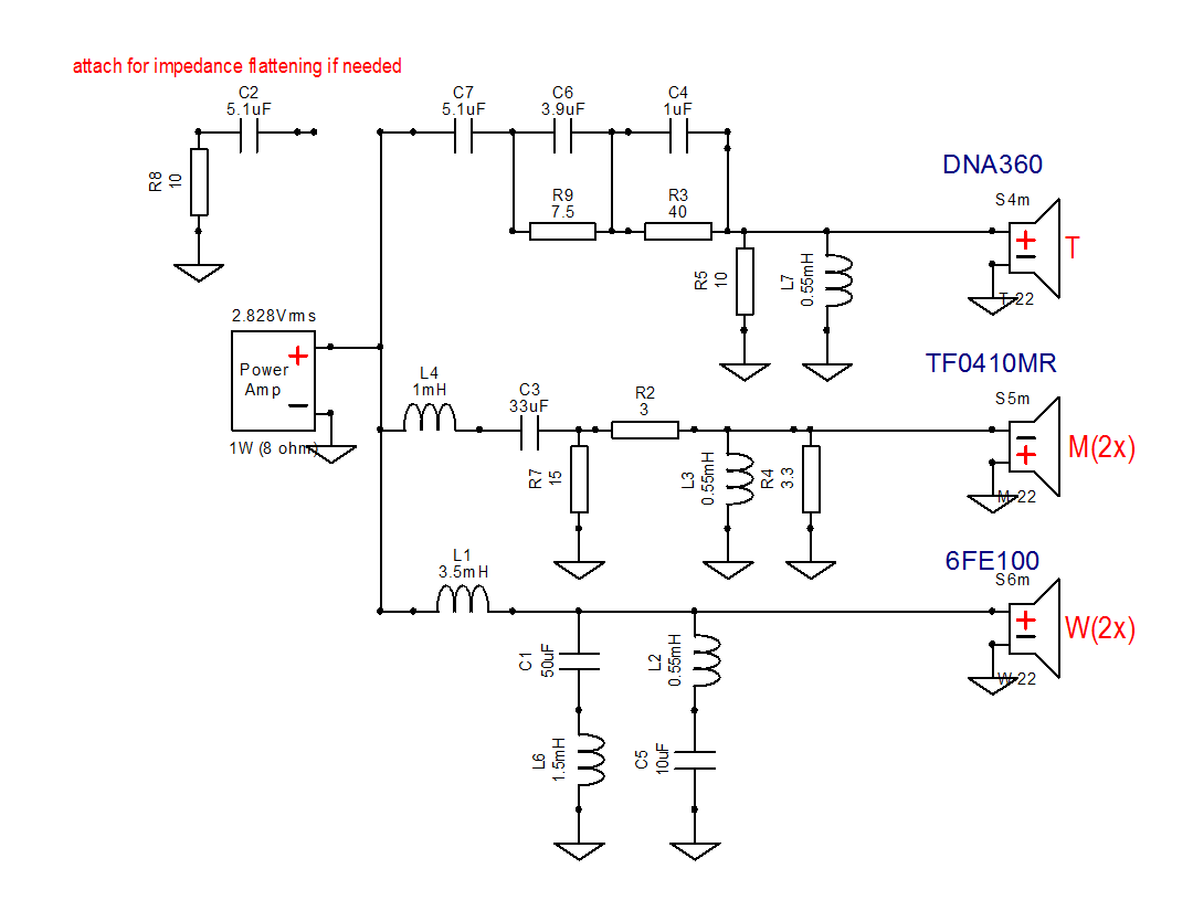
L1 need to have low series resistance (an iron core is a good idea here). The other inductors aren’t so critical and can be made from 20 gauge wire or even smaller.
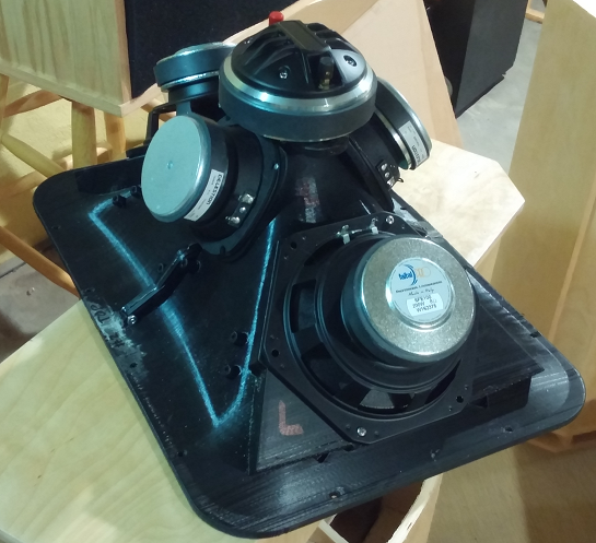
The impedance curve for the speaker looks like this:
The high impedance in the treble can be reduced to around 12 ohms with the flattening circuit shown in the crossover schematic if you want (say if you’re using an amp with highish output impedance).
L1 need to have low series resistance (an iron core is a good idea here). The other inductors aren’t so critical and can be made from 20 gauge wire or even smaller.
The impedance curve for the speaker looks like this:
The high impedance in the treble can be reduced to around 12 ohms with the flattening circuit shown in the crossover schematic if you want (say if you’re using an amp with highish output impedance).
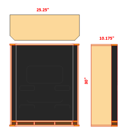
Here is a pdf file showing how to cut the wood panels for the cabinet I used. It uses a “Onken”-like type of shelf bass porting (large vent size relative to driver size). The sides are tapered to help reduce mid frequency diffraction and because I like the way it looks.
http://libinst.com/SynergyDIY/3DP%20version/DIYAudio/Files/Cabinet%20Plans.pdf
The grill is plastic window screen stretched over ¼” plywood that mounts around the waveguide lip (which sticks out from the baffle) and within the shallow cabinet lips. With the grill board in place (mounted with a few screws), the cabinet edges become essentially flush with the waveguide mouth, done to try to minimize diffractions there.
When mounting the waveguide, the screws should be angled away from the center so that they grab enough wood. The lips of the guide are narrow and the holes are near their edges. You might even want to cut the opening in the baffle a little smaller and then cut it wider with a 45degree router bit if you have the tools. Don’t forget to use rubber gasket tape on the waveguide before mounting.
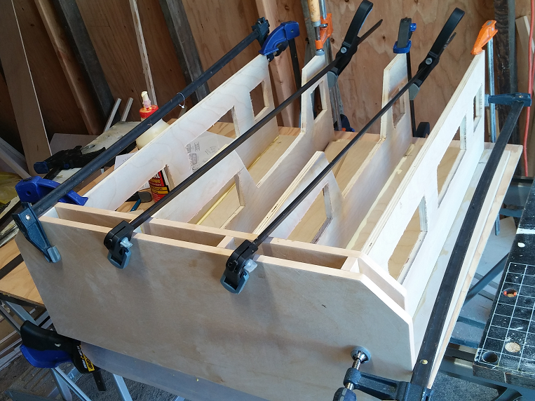
I have a small sheet of cotton (‘bluejean’) insulation in the cabinet behind each woofer for damping. I also used 3 thicknesses of the same behind the tweeter driver (DNA360), so that it gets mashed between driver and the back of the cabinet. That helps damp both the baffle and the back panel. With that and with all the inner bracing, the cabinet is pretty solid and well behaved.
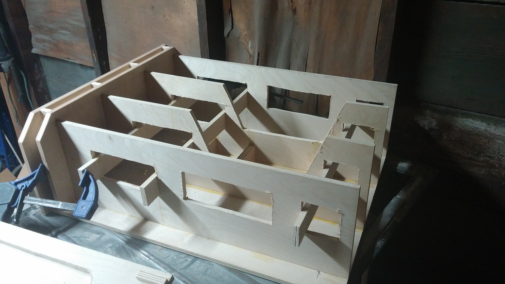
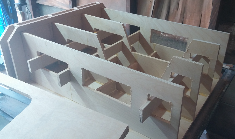
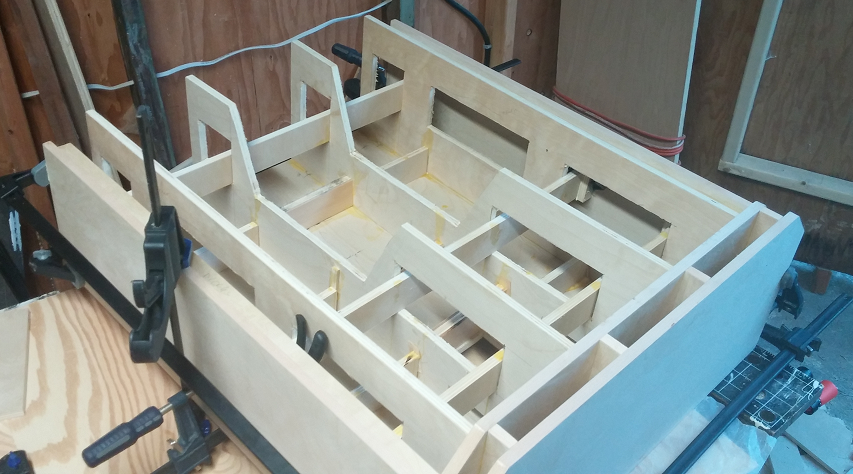
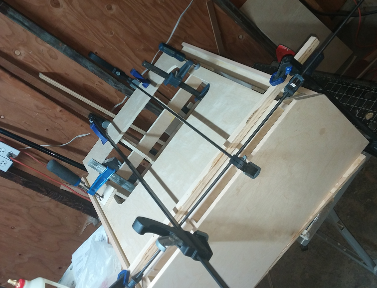
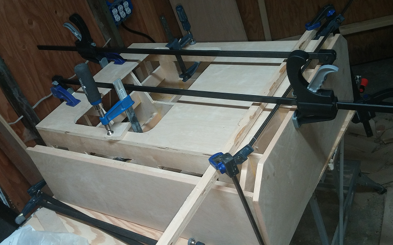
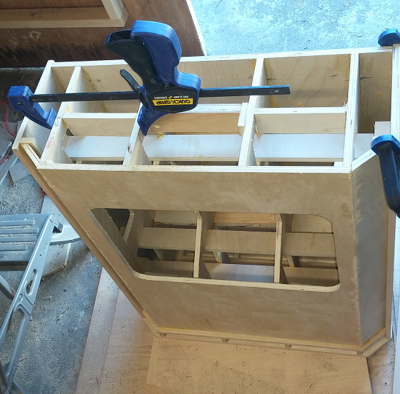
Here are a bunch of pictures I took during assembly of the cabinet, showing how it goes together and the use of internal bracing. Get lots of clamps! I opted to design for thinner (1/2”) plywood and lots of “matrix” bracing rather than thick plywood. I think that works better and also weight is an issue for me, I need to be able to move or carry these.
http://libinst.com/SynergyDIY/3DP%20version/DIYAudio/Files/Cabinet%20Plans.pdf
The grill is plastic window screen stretched over ¼” plywood that mounts around the waveguide lip (which sticks out from the baffle) and within the shallow cabinet lips. With the grill board in place (mounted with a few screws), the cabinet edges become essentially flush with the waveguide mouth, done to try to minimize diffractions there.
When mounting the waveguide, the screws should be angled away from the center so that they grab enough wood. The lips of the guide are narrow and the holes are near their edges. You might even want to cut the opening in the baffle a little smaller and then cut it wider with a 45degree router bit if you have the tools. Don’t forget to use rubber gasket tape on the waveguide before mounting.
I have a small sheet of cotton (‘bluejean’) insulation in the cabinet behind each woofer for damping. I also used 3 thicknesses of the same behind the tweeter driver (DNA360), so that it gets mashed between driver and the back of the cabinet. That helps damp both the baffle and the back panel. With that and with all the inner bracing, the cabinet is pretty solid and well behaved.
Here are a bunch of pictures I took during assembly of the cabinet, showing how it goes together and the use of internal bracing. Get lots of clamps! I opted to design for thinner (1/2”) plywood and lots of “matrix” bracing rather than thick plywood. I think that works better and also weight is an issue for me, I need to be able to move or carry these.
An externally hosted image should be here but it was not working when we last tested it.
An externally hosted image should be here but it was not working when we last tested it.
An externally hosted image should be here but it was not working when we last tested it.
An externally hosted image should be here but it was not working when we last tested it.
An externally hosted image should be here but it was not working when we last tested it.
An externally hosted image should be here but it was not working when we last tested it.
An externally hosted image should be here but it was not working when we last tested it.
An externally hosted image should be here but it was not working when we last tested it.
An externally hosted image should be here but it was not working when we last tested it.
An externally hosted image should be here but it was not working when we last tested it.
Here are a bunch of pictures taken of the waveguide during final installation of drivers and crossover boards. The two halves of the waveguide attach together with JBWeld (steel epoxy) glue and screws.
To attach the plastic halves together: 2x 8-32x3/4” bolts and nuts; and 2x 4-40x2” bolts and nuts. Use blue threadlock fluid to keep the nuts from loosening.
The crossover board, midranges, and woofers attach with #6 sheet metal screws (pre-drill the holes in the plastic waveguide with a 0.11” drill so the screws will go in without cracking but will still hold tight). Length of the sheet metal screws needed are 3/8” and 5/8” (no longer than needed in each location).
An externally hosted image should be here but it was not working when we last tested it.
An externally hosted image should be here but it was not working when we last tested it.
An externally hosted image should be here but it was not working when we last tested it.

Thanks for trying. The Gallery is not open for new images at the moment because it was causing server problems and we didn't want another crash. Same with the Wiki.I
BTW, I had planned to put all these pix in the diyaudio.com gallery, but it no longer accepts new photos so these are being hosted from my own website.
You can still attach images and place them inline with your text, this little thread will show yo how.
How to embed pictures in the post text?
")
What an awesome share! Hats off to you, sir! I do hope we will get to see a few of them being build.
Out of curiosity I uploaded the model to Shapeways to see it's pricing, it's about € 525,00. (white Flexible PA material, one of the cheapest materials available) That's only for one half... Buying a printer and printing it will be cheaper. There should be cheaper sources, sometimes i.materialise has better pricing, but for these sizes the commercially available printing industry often is way too expensive.
Out of curiosity I uploaded the model to Shapeways to see it's pricing, it's about € 525,00. (white Flexible PA material, one of the cheapest materials available) That's only for one half... Buying a printer and printing it will be cheaper. There should be cheaper sources, sometimes i.materialise has better pricing, but for these sizes the commercially available printing industry often is way too expensive.
Last edited:
Out of curiosity I uploaded the model to Shapeways to see it's pricing, it's about € 525,00... That's only for one half.
And here I was feeling bad for the guy who was going to stuff his crossover with V-Caps.
Thanks for posting all the details.
I intend to build it, don't have a 3d printer atm though so I need to get on top of that first & building things in autumn/winter in London is miserable so I hope this will be my job for next spring/summer.
Good to hear! Getting a 3D printer with right hotend and how to make it behave will take you a month or more, and is an indoor project, so autumn/winter is prime time to get that going.
3D printing, especially after you learn a little how to make design files in F360, gives you a nice "I can do ANYTHING" feel, opens up things you can do immensely!
After making the horn, the DNA360 just worked better in it. Both went low enough, but the DNA360 was considerably smoother (had more output, too, but either were still strong enough to work with the woofers). Easier to smooth the frequency response, basically.
with Peerless/Tympany:

with DNA360:

with Peerless/Tympany:
with DNA360:
Now that you have the shape built, you could always make a mold and do casting with these- or find a manufacturer for the task. There'd be a fairly high price some would gladly pay for this level of performance, so while you'd have high initial investment, each waveguide could easily be sold for $100+.
The way it is shaped, I don't think a mold could work (there are cavities under surfaces and other features that wouldn't allow a mold to release). Except for a lost wax mold (or similar) but then it would probably be more expensive than 3D printing to do. Or if it were molded in multiple parts and then glued together. But my understanding is that making injection molds for something this big (or multiple things adding up to something this big) is in the range of $20k or more.
- Home
- Loudspeakers
- Multi-Way
- 3D printed 3-way Unity waveguide home audio speaker