Why so slow on printing though? What goes wrong if you go faster?
The axial fans don't push air as well as the blower style (according to what I've read... But no actual expertise on that...).
I'd think you need all the air you can get, to cool the 9x the plastic put down per linear mm travel (compared to most printers that use 0.4mm nozzles).
The axial fans don't push air as well as the blower style (according to what I've read... But no actual expertise on that...).
I'd think you need all the air you can get, to cool the 9x the plastic put down per linear mm travel (compared to most printers that use 0.4mm nozzles).
Why so slow on printing though? What goes wrong if you go faster?
The axial fans don't push air as well as the blower style (according to what I've read... But no actual expertise on that...).
I'd think you need all the air you can get, to cool the 9x the plastic put down per linear mm travel (compared to most printers that use 0.4mm nozzles).
I should have mentioned that I'm using 0.8mm layer heights and a 1.4mm line width, so 12x as much PLA as when I was printing with a 0.4mm nozzle at 0.2mm layer heights. I haven't tried lowering the layer heights to say 0.6mm - that should allow me to print a bit faster.
I suffer a couple of issues when printing faster: at points in the print, the PLA doesn't grab the layer below, especially at corners or curved overhangs (resulting in sagging on the latter), and the nozzle almost seems to drag the PLA along until it reaches a point it starts to stick to (i.e., a straighter section where I have no problems); a similar problem occurs at layer starts; and the extruder starts to skip steps. I've increased the PLA temperature a bit to see how that helps, and played endlessly with the retraction, extra prime, combing, etc. settings, and while some of these help, they don't let me bump up the speed that much.
I'm wondering if I should drop down to the 1mm or 0.8mm nozzle and print at lower layer heights, but at faster speeds. More experimenting ...
Would anyone do a print job for me? Please message me. Thanks
Because the shipping is way more expensive than the PLA, it often makes sense to find someone locally on Craigslist to print your design.
The E3D Volcano eruption pack includes a 40W element. Ive also seen somewhere a 50W element for 12V and a 60W for 24V
Unfortunately it looks like the volcano packs are not consistent in this regard. MatterHackers doesn’t offer a 40W element (mine are 30W) but now that I’ve looked, I’ve found some eBay retailers who do. Wish I had been more thorough.
If you're on Amazon Prime, you can get 5 of them delivered 2day for 9 bucks
Amazon.com: WAHHING 5pcs 6X20mm 1M 12V 40W Ceramic Cartridge Heater Wire For 3D Printer Reprap Prusa: Industrial & Scientific
No idea what to do with the 4 spares though...
Amazon.com: WAHHING 5pcs 6X20mm 1M 12V 40W Ceramic Cartridge Heater Wire For 3D Printer Reprap Prusa: Industrial & Scientific
No idea what to do with the 4 spares though...
I checked Amazon and they have some 50W heater cartridges too. Shipping for those is kind of slow, though (coming from Far East, I assume). And one 60W heater if you're on a 24V system.
You can check the DC resistance of your cartridge, should measure 3.6 ohms (12V system) if 40W; or 4.8 ohms if 30W. 4x those values if on a 24V system.
Odd that they'd ship just a 30W with the 'eruption pack'. I got clones, which came with the 40W. I may order a 50W just to have it available.
You can check the DC resistance of your cartridge, should measure 3.6 ohms (12V system) if 40W; or 4.8 ohms if 30W. 4x those values if on a 24V system.
Odd that they'd ship just a 30W with the 'eruption pack'. I got clones, which came with the 40W. I may order a 50W just to have it available.
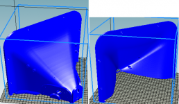
Hi bwaslo. I was looking into printing this for a member here, but when I imported the horn half into my slicer, it appears the horn is larger than my 300mm print bed
Is the model intended to printed the scale that the STL files open in?
Thanks for your work, this looks like an awesome project. I was going to do one for myself.
Is the model intended to printed the scale that the STL files open in?
Thanks for your work, this looks like an awesome project. I was going to do one for myself.
Here it the file with the diagonal positioning, might make your slicer more happy!
http://libinst.com/3DP/WG4%20positioned.stl
http://libinst.com/3DP/WG4%20positioned.stl
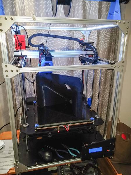
Wow Bill, I’ve been following your FT-5 build history so closely I can tell that that’s a pretty old picture of your printer in action. In that photo you still have the front crossbar, wire chain, bed clips and the blue parts cooler you sent me.
I made some progress with the build (exactly halfway through the assembly manual) but had to put it on hold due to some unexpected (but welcome) work coming my way. I already have a revised list of (more) parts to order so I can definitely use the money. In fact, I think I’m convinced a Raspberry Pi-based setup is the way to go. I’ll ask you more about that when the time comes.
My FT-5 R2 kit doesn’t seem to be missing anything. The only issue I had so far was one of my ACM parts (FT-8) not fitting against one of the rails correctly. I had to file it a bit to square it up.
I can already see what you mean about the hobby taking over your life. I really wish I had just replaced as much as possible with 713maker parts. I still might, which is why I haven’t used loctite on any screws. Speaking of which, the t-nuts take a little while to master installing. Still not sure if the ones I can’t see are spanning the crossbar.
Overall, I’m taking my time and enjoying the build. Pretty serene experience so far, but I expect there are some frustrations laying in wait for me.
Sounds like progress (and the expected lots-of-work), Brinkman.
I actually still have one of the cable chains still on (the x), too lazy to replace that one so far. If/when it breaks another wire, I'll do it then. But if I were building new, I wouldn't use either chain, it's hard to fit all the wires that you might want in them and they're just unnecessary (though pretty) trouble waiting to happen.
The T-Nuts have a trick to them -- get them threaded on the screw and then back off on the screw pretty far but not far enough to come off the threads. Then quickly spin the driver clockwise, the T-Nut will spin into position. Then keep turning clockwise till tightened. Works pretty much all the time. If you thread the screw in slowly it might or might not work, but fast when not too-far-in yet works.
I really like the Octopi setup, but then I'm lazy so I like controlling and watching the printer from my armchair. Just DON'T print from USB of a Windows computer that is connected to the web (Win10 in particular) -- the hard-to-avoid automatic updates would drive you nuts and ruin a lot of prints! A lot of people like to print from the SD card that is on the printer, but I didn't want to mess with moving files back and forth via those little cards.
In the (unlikely) event that someone is printing the waveguide for this, and wants to do a version without the woofers mounted onto the horn, here is an STL file without the woofer mounts --
If I were to make the speaker again, I'd do it with the woofs mounted inside the cabinet (instead of on the waveguide body), mounted facing toward the outsides with output exiting through slots to either side of the waveguide. I think that would work slightly better for the "array trick" of extending horizontal directivity, and be an easier waveguide to 3D print. It wouldn't have the advantage of all drivers mounted onto the same removable assembly, but since it wouldn't be removed often, if at all, that's probably not important.
If I were to make the speaker again, I'd do it with the woofs mounted inside the cabinet (instead of on the waveguide body), mounted facing toward the outsides with output exiting through slots to either side of the waveguide. I think that would work slightly better for the "array trick" of extending horizontal directivity, and be an easier waveguide to 3D print. It wouldn't have the advantage of all drivers mounted onto the same removable assembly, but since it wouldn't be removed often, if at all, that's probably not important.
Attachments
- Home
- Loudspeakers
- Multi-Way
- 3D printed 3-way Unity waveguide home audio speaker