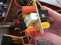
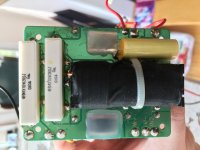
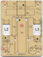
Can someone help me with drawing a schematic for my Boston Acoustics VR-M60? BA doesn't share schematics unfortunately, and I'd like to see this crossover in schematic form to get a better idea of what components do what.
I tried and got very discouraged based on the number of components and things in parallel, but then seem to be crossing over to the other side (it's a bi wired design)
I'm trying to gain a full understanding of the circuit and what component does what, etc.
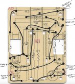
I tried tracing the board, and still got confused trying. Anyone else good at this?
At the end, I want to have 2 "separate" crossovers. 1 for the high and 1 for the low. Not 2 separate physical crossovers, just schematics if possible.
I tried and got very discouraged based on the number of components and things in parallel, but then seem to be crossing over to the other side (it's a bi wired design)
I'm trying to gain a full understanding of the circuit and what component does what, etc.
I tried tracing the board, and still got confused trying. Anyone else good at this?
At the end, I want to have 2 "separate" crossovers. 1 for the high and 1 for the low. Not 2 separate physical crossovers, just schematics if possible.
Attachments
First, try using XSim. I like it and it is simple.
Next, try this link:
A Speaker Maker's Journey: Crossover Basics
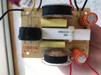
It will also help you that in general, the smallest caps will be going to the tweeter, the largest caps on the woofer.
Best,
E
Next, try this link:
A Speaker Maker's Journey: Crossover Basics
It will also help you that in general, the smallest caps will be going to the tweeter, the largest caps on the woofer.
Best,
E
Last edited:
")
That you both for the help. It’s amazing how quickly you guys respond.
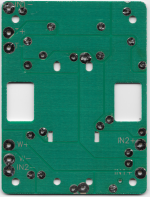
4real, how did you over lay the foil side on the component side?
Tauntran, how were you able to follow the traces and draw the schematic? I’m able to draw basic schematics from basic board layouts, but this had things crossing over each other, and things things I thought were for the tweeter were tracing to the woofer’s input, etc and I became discouraged.
Thanks guys!!
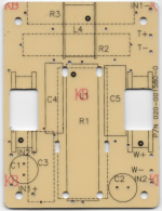
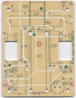
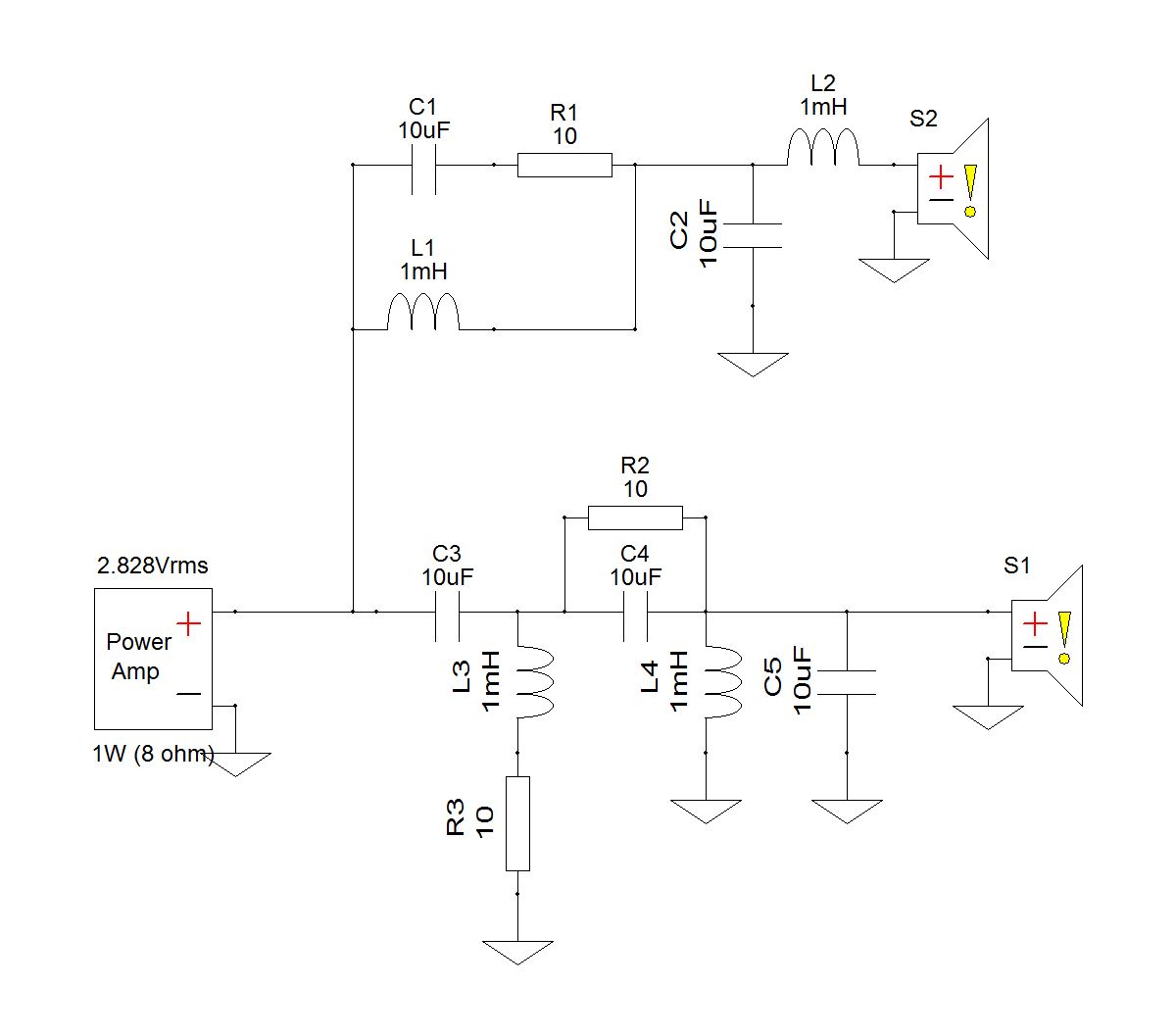
So, it seems parts are numbered from the woofer side, not the tweeter and I labelled my parts accordingly. They will be different from yours.
C1/R1/L1 form a baffle step compensation circuit (BSC) while L1 forms the traditional first pole of the low pass filter.
C3/L3/C4/L4 form a traditional fourth order high pass filter. There are additional components doing some frequency shaping. R2 and C5 are a little unusual. Of course, I could have misread much.
R3 appears to be there just to keep L3 from showing a dead short to ground, and is a typical solution.
Attachments
Just some basic Photoshop masking, flipping and blending. Actually you did most of the hard work by providing so perfectly aligned images 😜4real, how did you over lay the foil side on the component side?
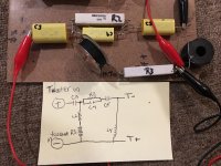
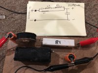
Thanks guys for the replies. Somehow after looking at your drawings and also the 4real's photoshopped image, I was able to figure it out. It seems that there are errors in both eriksquires and tuantran's schematics assuming I read the board correctly. I tried following riksquires and tuantran's and got confused, but both separated things enough for me, I went on my own. I even wired them up as shown, and they sound exactly the same as they do on the PCB.
Attachments
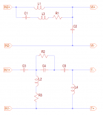
Now that we have a schematic, can someone explain how it works? It’s amazing what the crossover does. Connecting the woofer directly to the amp sounds much different that connecting with its crossover. Even connecting the woofer to the tweeter’s crossover makes it sound like a tweeter. Didn’t experiment with the tweeter since low frequencies could damage it. In the tweeter crossover, C3 let’s high frequencies pass, and then the resistor reduces the volume to match the tweeter with the woofer...? What’s all the other stuff?
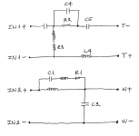
For the low pass (going to the woofer), L1 and C2 form a 2nd order filter with the woofer (the woofer's resistance being the R in the LRC filter). C1, L3 and R1 form a notch filter. This either corrects the phase of the woofer with the tweeter at some point a little after the crossover frequency, or corrects a peak in the woofer's response at some frequency above the crossover frequency, or both. When I say above, it is likely to be above but near the crossover frequency. This could also help correct for baffle influence, depending on the width of the notch.
For the high pass, C3 forms a first order filter with L2, R3, R2, and C4 correcting the impedance of the tweeter (including the impedance of C5 and L4). This is followed by C5 and L4 which form a 2nd order filter.
I'm not a crossover expert, but this is my guess. It also depends on the values of the components.
- Status
- This old topic is closed. If you want to reopen this topic, contact a moderator using the "Report Post" button.
- Home
- Loudspeakers
- Multi-Way
- Help Drawing a Schematic