Hi all,
I got a pair of 6.5" midbass drivers made locally, from a manufacturer which is not exactly famous for high quality. I am trying to build a pair of small speakers with budget drivers, to see what sound quality I can get.
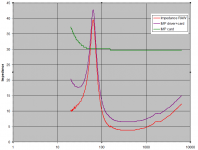
When I do the impedance measurement in free air (I'm using ARTA LIMP), I get the following curves:
The impedance below 50Hz is strange, to say the least. I don't remember seeing this shape in any other driver. As you can see, the two drivers are quite close to each other -- piece-to-piece consistency is pretty good. The Fs in the graph is about 54Hz, which is close to the published 49Hz figure.
ARTA LIMP goes bonkers when I ask it to calculate T/S parameters -- it seems to go into an infinite loop. I'm talking to Ivo, the creator of ARTA about it. If I reduce the frequency range from 20-20K to 35-20K, LIMP works well and I get the T/S parameters (sans Vas). But this may not be an adequate solution, since I'll need to calculate the Vas too, and for that, I need to get two graphs, and I don't know how LIMP will behave when I have two graphs both looking weird like this.
My question is not about ARTA. My question is: are these drivers "bad" or defective in design in any way? It's unlikely that they're defective in construction, since both have almost identical curves. It must be a defective design if at all.
Any ideas? Should I scrap these drivers and go for other models?
(I've just started using LIMP from the ARTA suite, but already I like it a lot, compared to Speaker Workshop.") )
)
I got a pair of 6.5" midbass drivers made locally, from a manufacturer which is not exactly famous for high quality. I am trying to build a pair of small speakers with budget drivers, to see what sound quality I can get.
When I do the impedance measurement in free air (I'm using ARTA LIMP), I get the following curves:
An externally hosted image should be here but it was not working when we last tested it.
An externally hosted image should be here but it was not working when we last tested it.
The impedance below 50Hz is strange, to say the least. I don't remember seeing this shape in any other driver. As you can see, the two drivers are quite close to each other -- piece-to-piece consistency is pretty good. The Fs in the graph is about 54Hz, which is close to the published 49Hz figure.
ARTA LIMP goes bonkers when I ask it to calculate T/S parameters -- it seems to go into an infinite loop. I'm talking to Ivo, the creator of ARTA about it. If I reduce the frequency range from 20-20K to 35-20K, LIMP works well and I get the T/S parameters (sans Vas). But this may not be an adequate solution, since I'll need to calculate the Vas too, and for that, I need to get two graphs, and I don't know how LIMP will behave when I have two graphs both looking weird like this.
My question is not about ARTA. My question is: are these drivers "bad" or defective in design in any way? It's unlikely that they're defective in construction, since both have almost identical curves. It must be a defective design if at all.
Any ideas? Should I scrap these drivers and go for other models?
(I've just started using LIMP from the ARTA suite, but already I like it a lot, compared to Speaker Workshop.
)
Last edited:
It looks like you have trouble measuring below 30hz. I doubt the measurement setup. Probably there is some high pass filtering in the setup that is limiting the lows.
I have measured drivers using LIMP and Xonar DX/D2X and never ran into 'infinite loop' kind of problems. I ve often had trouble measuring the lows because the impedance curve kept fluctuating near 20hz probably due to acoustic noise.
I have measured drivers using LIMP and Xonar DX/D2X and never ran into 'infinite loop' kind of problems. I ve often had trouble measuring the lows because the impedance curve kept fluctuating near 20hz probably due to acoustic noise.
Thanks a lot. I'll try this now.It looks like you have trouble measuring below 30hz. I doubt the measurement setup. Probably there is some high pass filtering in the setup that is limiting the lows.
I've never set the measurement range to start below 20Hz. I'll try that.It looks like you have trouble measuring below 30hz. I doubt the measurement setup. Probably there is some high pass filtering in the setup that is limiting the lows.
Just to point out a matter of detail: I don't get an infinite loop when I measure. I get it when I ask the software to calculate T/S parameters. And this is reproduced by Ivo too, using my .LIM file.I have measured drivers using LIMP and Xonar DX/D2X and never ran into 'infinite loop' kind of problems.
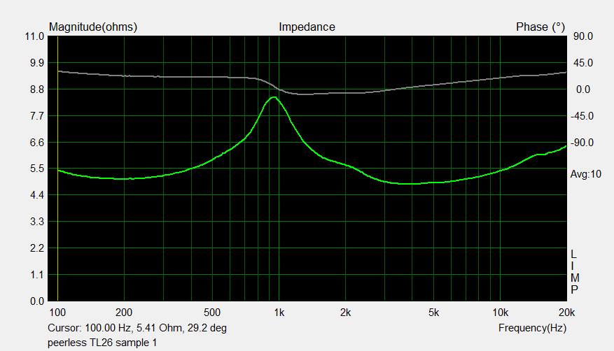
See this measurement, of a different driver:Measuring the resistance with a multimeter will give a more sensible 4 ohm reading, I'm quite sure. There must be a capacitor on the input of the ARTA software measurement.
An externally hosted image should be here but it was not working when we last tested it.
As you can see, the portion below the resonant peak goes down to "normal" levels, using the same measurement rig. The one below is that of a tweeter:
An externally hosted image should be here but it was not working when we last tested it.
I've measured quite a few other drivers, and their impedance curves all look "normal". I've also measured a resistor and capacitor, and gotten exactly the curves I'd expect to see. I can do it again if you want.
The only thing I've not done till now is extend the low end of the frequency range below 20Hz. I'll do that too.
PROBLEM SOLVED!
Thanks to all of your inputs, and to Ivo's patient guidance over email, the problem has been solved. It was the USB audio interface.
I first did a measurement of a 27 Ohm power resistor using the hardware and software I was using till now, just increasing the frequency range to 5Hz. This is what I got.

From the graph, it appeared that there was a capacitor in series with the load somewhere and at low frequencies, it was increasing the impedance. At this point, I guessed that this was not my laptop or software, it had to be the audio interface. So I kept aside the Behringer UCA202 I was using earlier, and fished out my earlier USB audio interface, a venerable 12-year-old Creative SoundBlaster Digital Music, bought in perhaps 2004 or so. I had retired it after buying the UCA202. After searching for and downloading modern device drivers for it, and after fiddling with controls of various kinds, and rebooting a few times, I got the impedance jig to work with the same 27 Ohm resistor:

Here, if anything, the series capacitor effect has been replaced with a series inductor -- the impedance actually drops below 20Hz. I was thrilled -- I could now try the drivers with the new interface.
So, here's the 5.25" driver I had used earlier as a test, now with the Creative SB interface:

And finally, the driver whose graph had started it all: the 6.5" driver:

Thanks to all of you, I think the problem is licked. I am getting fairly consistent readings when switching between FFT and stepped-sine methods. All is now well.
Thanks to all of your inputs, and to Ivo's patient guidance over email, the problem has been solved. It was the USB audio interface.
I first did a measurement of a 27 Ohm power resistor using the hardware and software I was using till now, just increasing the frequency range to 5Hz. This is what I got.
From the graph, it appeared that there was a capacitor in series with the load somewhere and at low frequencies, it was increasing the impedance. At this point, I guessed that this was not my laptop or software, it had to be the audio interface. So I kept aside the Behringer UCA202 I was using earlier, and fished out my earlier USB audio interface, a venerable 12-year-old Creative SoundBlaster Digital Music, bought in perhaps 2004 or so. I had retired it after buying the UCA202. After searching for and downloading modern device drivers for it, and after fiddling with controls of various kinds, and rebooting a few times, I got the impedance jig to work with the same 27 Ohm resistor:
Here, if anything, the series capacitor effect has been replaced with a series inductor -- the impedance actually drops below 20Hz. I was thrilled -- I could now try the drivers with the new interface.
So, here's the 5.25" driver I had used earlier as a test, now with the Creative SB interface:
And finally, the driver whose graph had started it all: the 6.5" driver:
Thanks to all of you, I think the problem is licked. I am getting fairly consistent readings when switching between FFT and stepped-sine methods. All is now well.
Last edited:
From the graph, it appeared that there was a capacitor in series with the load somewhere and at low frequencies, it was increasing the impedance.
I have UCA222 and never managed to get reliable impedance curves. Apart from the cap there is also a series resistor at the output.
A series resistor actually shouldn't make a difference to the readings, because the measurement method just measures the voltage at a potential divider, comparing the DUT with a fixed known impedance. It's the non-linear impedance in series, like a cap, which causes problems, I think.I have UCA222 and never managed to get reliable impedance curves. Apart from the cap there is also a series resistor at the output.
Does LIMP take a calibration file the way SPL measurement software takes a mic calibration file? I've never seen any mention of this in the documentation.Maybe you could compensate by creating a zma file that would straiten it out.
A series resistor actually shouldn't make a difference to the readings, because the measurement method just measures the voltage at a potential divider, comparing the DUT with a fixed known impedance. It's the non-linear impedance in series, like a cap, which causes problems, I think.
The measurement technique needs the reference sound card output along with the one measured across the DUT. The former is needed right after the soundcard output BEFORE any resistor. http://www.diyaudio.com/forums/clas...-audio-amp5-tripath-ta2022-15.html#post986498.
Since that is not available with UCA222 (probably UCA202 as well) hence impedance measurements are not reliable. Probably an extra amp can fix this, I ve not tried though.
imp meas with amp.png
Wow, thanks. Yes, this should work. I guess I was just plain lucky to have a second audio interface lying around and I just swapped. But if not, then the subtraction route should work I guess.Appears that one can make it work in excel simply by subtracting curves from each other. Probably 4 ohm unit. I did that with a tracing software, then copied with notepad++ into Excel.
I tried reading this thread, but couldn't see why the output resistor should cause a problem.The measurement technique needs the reference sound card output along with the one measured across the DUT. The former is needed right after the soundcard output BEFORE any resistor. http://www.diyaudio.com/forums/clas...-audio-amp5-tripath-ta2022-15.html#post986498.
From what I understand of the impedance jig, it just measures a ratio[/] of voltages. One voltage is just "above" the reference resistor, the other is between the reference and DUT.
When measuring the ratio, there should be no impact of any impedance change outside this pair of devices, right? We are not measuring absolute voltages here, just measuring the ratio of two voltages.
I think you are spending too much time fretting about some hardware glitches on the bottom end of the frequency response.
With a typical 6.5" 4 ohm paper driver, like the extremely similar Visaton W170S 4 ohm, you are likely to end up with a circuit like this:
ALTO I
This is where you are going.
With a typical 6.5" 4 ohm paper driver, like the extremely similar Visaton W170S 4 ohm, you are likely to end up with a circuit like this:
ALTO I
This is where you are going.
Yes, the bottom end below 40Hz is of little interest in most measurements but it was preventing me from calculating the T/S parameters. Now, that's a bit of a show-stopper for speaker design, isn't it? [emoji2]I think you are spending too much time fretting about some hardware glitches on the bottom end of the frequency response.
- Status
- This old topic is closed. If you want to reopen this topic, contact a moderator using the "Report Post" button.
- Home
- Loudspeakers
- Multi-Way
- Are these drivers defective?