Hey there!
I've read trough all the synergy posts I could find on the forum and learned very much about the concept thanks to you guys!
I'd like to thank the developers of xsim and hornresp and mr.Danley for his work on multiple entry horns!
My synergy horn build consists of
1x1" BMS4550
4x4" Celestion TF0410MR
2x10" 18Sound 10W500
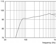
After playing around with the filter feature in Hornresp, I came to a point where the response is pretty flat.
For that I only use a high pass on the horn and a high pass on the mid.
As far as I understand and see from the simulations, the position of the entry points acts like an acoustic bandpass filter.
So is it necesary to lowcut the midrange speaker, as the horn already does that acousticly?
Does anybody have any observations?
Here's snaps from the Hornresp simulations:
Horn Dimensions:

Tweeter (BMS4550) 1"

Midranges (Celestion TF0410MR) 4"

Woofers (18Sound 10W500) 10"

Snaps from XSim:
Here's the layout:

Highpass at 2000Hz on the Tweeter
Highpass at 500Hz on the Mids
Lowpass at 500Hz on the Woofer
Frequency response of the filter

Cut it at 2k so it so it's easier to compare with the Hornresp freq response.
It's pretty flat from 2k on both frequency and phase wise.
The resistors are for some padding on the tweeter and midrange.
What do you guys think?
I've read trough all the synergy posts I could find on the forum and learned very much about the concept thanks to you guys!
I'd like to thank the developers of xsim and hornresp and mr.Danley for his work on multiple entry horns!
My synergy horn build consists of
1x1" BMS4550
4x4" Celestion TF0410MR
2x10" 18Sound 10W500
After playing around with the filter feature in Hornresp, I came to a point where the response is pretty flat.
For that I only use a high pass on the horn and a high pass on the mid.
As far as I understand and see from the simulations, the position of the entry points acts like an acoustic bandpass filter.
So is it necesary to lowcut the midrange speaker, as the horn already does that acousticly?
Does anybody have any observations?
Here's snaps from the Hornresp simulations:
Horn Dimensions:
Tweeter (BMS4550) 1"
Midranges (Celestion TF0410MR) 4"
Woofers (18Sound 10W500) 10"
Snaps from XSim:
Here's the layout:
Highpass at 2000Hz on the Tweeter
Highpass at 500Hz on the Mids
Lowpass at 500Hz on the Woofer
Frequency response of the filter
Cut it at 2k so it so it's easier to compare with the Hornresp freq response.
It's pretty flat from 2k on both frequency and phase wise.
The resistors are for some padding on the tweeter and midrange.
What do you guys think?
I think you've got a good start here. But having recently completed a Synergy, I can see some things you need to do to improve your modeling.
What is the area of the 1" dia exit of the BMS4550.? After you drill out the square, its 5.08 cm2, so S1 in the HR model should be changed.
The BMS4550 has a 6.5 cm or so internal acoustic path length. The sound goes this deep into it before it bounces back to form a cancellation null with the mids. You should add this 6.5 cm plus the thickness of your CD mounting plate to the L12 in the HR model. (I did this then subtracted 1 cm from the resulting L12 to correlate measurements with my model).
Do these two things and you will get much better agreement between model and measurement at the individual driver level. I think also that then you will realize you need the mid/tweeter XO not too much above 1 Khz. That is not a problem for the BMS4550, but you might find in listening tests that a 12 db slope isn't steep enough with this low of a crossover.
Why do your 10" woofers start rolling off at 200 Hz? I'm guessing you could get them flat down below 80 Hz if you went bass reflex rather than sealed.
Do you need a low pass on the mids? Yes, its already attenuated by the bandpass chamber but you likely need additional filtering carefully chosen to provide a complementary slope to that on the tweeter.
A passive crossover ? That is brave !") How are you going to time align the tweeter with the mid and the woofer? Driver time alignment is another constraint on how far down the horn you place the mid and woofer entry points. With an active XO and DSP you could just dial in the delays needed for time alignment. With a passive XO its much harder.
How are you going to time align the tweeter with the mid and the woofer? Driver time alignment is another constraint on how far down the horn you place the mid and woofer entry points. With an active XO and DSP you could just dial in the delays needed for time alignment. With a passive XO its much harder.
Can time alignment be modeled in HR? I haven't done it but perhaps you can estimate the physical path lengths from each driver's voice coil (its nominal acoustic center) to its horn entry point, translate those lengths into time delays at the speed of sound and include them in the HR models as delays. Then HR will give you a better idea about how well your crossover filters and driver entry point locations work together. You can then vary filter parameters and driver entry point location to try and get a better response.
What is the area of the 1" dia exit of the BMS4550.? After you drill out the square, its 5.08 cm2, so S1 in the HR model should be changed.
The BMS4550 has a 6.5 cm or so internal acoustic path length. The sound goes this deep into it before it bounces back to form a cancellation null with the mids. You should add this 6.5 cm plus the thickness of your CD mounting plate to the L12 in the HR model. (I did this then subtracted 1 cm from the resulting L12 to correlate measurements with my model).
Do these two things and you will get much better agreement between model and measurement at the individual driver level. I think also that then you will realize you need the mid/tweeter XO not too much above 1 Khz. That is not a problem for the BMS4550, but you might find in listening tests that a 12 db slope isn't steep enough with this low of a crossover.
Why do your 10" woofers start rolling off at 200 Hz? I'm guessing you could get them flat down below 80 Hz if you went bass reflex rather than sealed.
Do you need a low pass on the mids? Yes, its already attenuated by the bandpass chamber but you likely need additional filtering carefully chosen to provide a complementary slope to that on the tweeter.
A passive crossover ? That is brave !
How are you going to time align the tweeter with the mid and the woofer? Driver time alignment is another constraint on how far down the horn you place the mid and woofer entry points. With an active XO and DSP you could just dial in the delays needed for time alignment. With a passive XO its much harder.Can time alignment be modeled in HR? I haven't done it but perhaps you can estimate the physical path lengths from each driver's voice coil (its nominal acoustic center) to its horn entry point, translate those lengths into time delays at the speed of sound and include them in the HR models as delays. Then HR will give you a better idea about how well your crossover filters and driver entry point locations work together. You can then vary filter parameters and driver entry point location to try and get a better response.
Thanks for the detailed comment nc535!
I've corrected the 1" entrance area and added the additional acoustic path distance to L12 Con
As for the XO for the tweeter áround 1k works best in the Hornresp simulation.
I also gave up on the idea of making it passive.
I'll get an UltraDrive and play around a bit so I can get a feeling of it
How do you model a ported horn?
I added a back volume to the 10" speaker record and ports that are the thickness of the ply.
Vrc:63
Lrc:15
Ap:30
Lpt:1.2 (I'm planing to use 12mm ply)

The units just arrived and I'm on the lookout for a place to cut and assemble the wood and for a good secondhand amp deal

I've corrected the 1" entrance area and added the additional acoustic path distance to L12 Con
As for the XO for the tweeter áround 1k works best in the Hornresp simulation.
I also gave up on the idea of making it passive.
I'll get an UltraDrive and play around a bit so I can get a feeling of it
How do you model a ported horn?
I added a back volume to the 10" speaker record and ports that are the thickness of the ply.
Vrc:63
Lrc:15
Ap:30
Lpt:1.2 (I'm planing to use 12mm ply)
The units just arrived and I'm on the lookout for a place to cut and assemble the wood and for a good secondhand amp deal
I'll get an UltraDrive and play around a bit so I can get a feeling of it
Or get a Mini-DSP 2x4HD (or two of them). Other than linear phase EQ at subwoofer frequencies, there's not much that you can't do with it. Want ideal linear phase impulse response? No prob.
It's just that I can get a used ultradrive for 1/2 the price of 1 minidsp
Well, that would be a pretty good price then, as the 2x4HD goes for about $200. But the Ultradrive doesn't do FIR filtering so you'll not likely get to linear phase response. (I'm not sure that really matters though -- the difference between linear phase and "usual multiway phase" response is one of those "I think I might hear it, maybe" things to my ears.
Try and vary the port size, port length and Vtc controls for the midrange in the wizard. You should be able to extend the bandpass response over a larger area and damp down the big peak.
I would agree that unless you plan to put some big pro woofers inside then 4 of the celestion mids is going to be more output than you need.
I would agree that unless you plan to put some big pro woofers inside then 4 of the celestion mids is going to be more output than you need.
Also, I'd look at scaling back the # of mids to 2. You have way more max output there than at any other point in the speaker (simplify the build!)
Also, fewer mids mean fewer port holes into the horn, which means less diffraction for the wavefront coming from the HF driver. I think having a separate mid (rather than trying to push everything from 300Hz up through the entire throat) is a good thing, because acoustic filtering is one of the major benefits of the Synergy/Unity approach. But in my recent horns (a.k.a. "Small Syns"), I use ONE midrange, and it is still more than adequate for my house or any non-showoffly-huge house I know of.
I try to understand why you can't get the 10" below 100hz, its freq. range is from 55-4000 and has extended upward HF range, you should use that to your advantage. You probably can get away with two celestions and make bandpass smaller like from 7/800hz - 1200hz if you can get them closer to the BMS. This way you get more power out of the celestions and BMS and less distortion.
I guess there is a trade of with synergy freq range you can use per driver.
I guess there is a trade of with synergy freq range you can use per driver.
i think that 10w500 driver can get below 100 Hz easily if vented.
Simulate it as an offset driver on a horn rather than an ME2, if you can't see how to do it as an ME2.
From a quick look, you might do better crossing to the woofer at 400 Hz rather than 500. That puts the large woofer holes further away from the apex and gives you more room to attenuate the pipe resonance of the woofer vent.
I try to understand why you can't get the 10" below 100hz, its freq. range is from 55-4000
It's not such a surprise if you look at the frequency response of the driver. 55Hz is the -10dB point.
Pro woofers don't have the correct TS parameters to go much lower without venting as nc535 said. Hifi woofers have better parameters to go lower but aren't used in PA applications because they don't have enough output. At home that is not such a consideration.
Attachments

How does one calculate the position of the vent along the horn?
nothing to calculate;
close to the mouth and in the corners is best
Using two woofers within 1/4 wavelength of each other will normally give 6dB increase over one alone. There can be horn gain in a synergy but usually not much if any for the woofer frequencies.isn't it so by using two woofers you gain a few DB more?
On a practical note,
I found a good deal on a Nova DC 8000.
It has EQ's on the inputs and Filters on the outputs.
I was wondering if one can use the the input EQ's by combining High Shelf and Low Shelf filters to alter the phase response.
As one would do using allpass filters.
I read quite a bit about allpass, but nowhere people say how they actually implement them in a digital crossover...
My synergy project is progressing slowly...
The woodworking part proved to be way harder than the sketchup part
An externally hosted image should be here but it was not working when we last tested it.
If you have a digital crossover you don't need all pass filters to delay one driver relative to another; you can implement delay directly.
But if you want to try all pass filters, download the "All-digital-coefs v1.2" file from minidsp ( I think that is where I got it). It has an APF tab.
But if you want to try all pass filters, download the "All-digital-coefs v1.2" file from minidsp ( I think that is where I got it). It has an APF tab.
- Home
- Loudspeakers
- Multi-Way
- Unity / Synergy Horn Build