I think I didn't express myself clearly.
I wasn't asking about delay between the separate units, but rather introducing phase shifts on the input in order to improve the linearity of the system.
And was wondering if playing around with the EQ will do the same as all pass filters do..
I wasn't asking about delay between the separate units, but rather introducing phase shifts on the input in order to improve the linearity of the system.
And was wondering if playing around with the EQ will do the same as all pass filters do..
that is typically done with a FIR filter. Download a copy of RePhase and look at the "paragraphic phase EQ" tab. you can draw and then implement an arbitrary phase curve filter. but before you do that dial in the amount of DSP delay between drivers that precisely aligns them in time - that will minimize the amount of phase change you need to introduce to get a flat phase curve
and yes, if you have a minimum phase response, then equalizing its frequency response to flat (and removing excess delay) will also flatten the phase curve.
and yes, if you have a minimum phase response, then equalizing its frequency response to flat (and removing excess delay) will also flatten the phase curve.
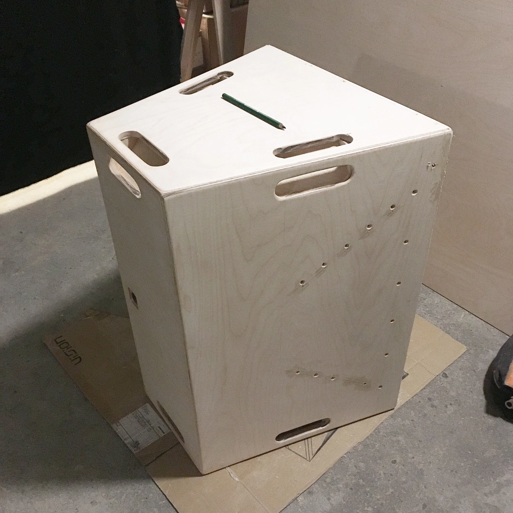
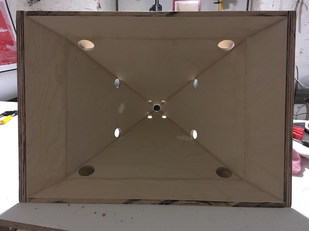
Is the noise because the holes are too small or because the surround is actually hitting against the horn wall at full excursion?
Just guessing from appearances, I'd say your mid holes are about right but the woofer holes look a little on the small side. Based on some sims I've done with 8" woofers, I'd expect >1" radius. But what does HornResp tell you?
Before making the holes larger, I would frustrumize them - taper the edges. This reduces the effective port length and can allow smaller holes to suffice. I would elongate them instead of simply drilling larger holes.
Before doing anything dramatic, do some THD measurements at various power levels.
Is the noise because the holes are too small or because the surround is actually hitting against the horn wall at full excursion?
Just guessing from appearances, I'd say your mid holes are about right but the woofer holes look a little on the small side. Based on some sims I've done with 8" woofers, I'd expect >1" radius. But what does HornResp tell you?
Before making the holes larger, I would frustrumize them - taper the edges. This reduces the effective port length and can allow smaller holes to suffice. I would elongate them instead of simply drilling larger holes.
Before doing anything dramatic, do some THD measurements at various power levels.
Here's what the SH-50 uses:
Midrange taps are 3/4" in diam, 3.5" from throat
Woofer taps are 2.5" in diam, 10.5" from throat
Woofer ports are 2.5" in diam, 14.5" from throat
Is there any benefit to smoothing those holes? Amazing to me they are so small!
It's just a plain ol' bandpass box. A pair of 2.5" ports have the same displacement as a single port that's 3.53" in diameter. And a 3.53" port is big enough for a 12" bandpass woofer, particularly when you consider that the box is tuned quite high. (The box is tuned to something like 80hz iirc)
I did some measurements today using the following setup:
REW with a loopback reference and a behringer measurement mic 1m from the speaker.
Here is an overlay plot of the responses of the Tweeter, Mids and Woofers:
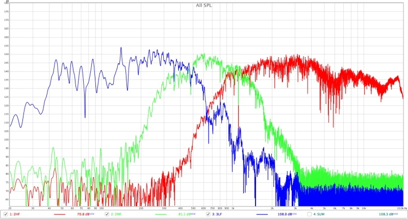
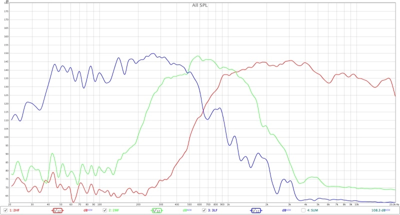
And a smoothed version of the same:
Sum of the responses:
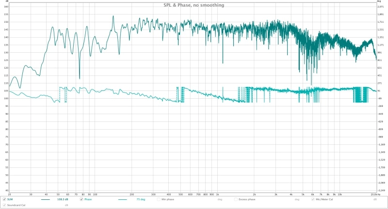
Windowed summed response (20ms Han) Frequency vs Phase
There is something weird happening around 6k that I have no explanation for.. it's a 10db dip with a weird jump in phase as well..
Not sure if it might have something to do with room reflection...
I guess I won't know before I do an outdoor measurement..
The low frequencies are combing quite a bit as well... I guess besides putting some absorber in the box, there is not much I can do about it?
What do you guys think?
Regarding the port noise, it is most present around 60hz when the air velocity is greatest at higher levels...
I played around with different values for the speaker port area and vent port area and will try to elongate them a tiny bit..
38,5 cm3 will go to 50 cm3 for the speaker port
63,6 cm3 will go to 142,4 cm3 for the vent port.
Thank you all for the help and the information you provide!
An externally hosted image should be here but it was not working when we last tested it.
REW with a loopback reference and a behringer measurement mic 1m from the speaker.
Here is an overlay plot of the responses of the Tweeter, Mids and Woofers:
And a smoothed version of the same:
Sum of the responses:
Windowed summed response (20ms Han) Frequency vs Phase
An externally hosted image should be here but it was not working when we last tested it.
There is something weird happening around 6k that I have no explanation for.. it's a 10db dip with a weird jump in phase as well..
Not sure if it might have something to do with room reflection...
I guess I won't know before I do an outdoor measurement..
The low frequencies are combing quite a bit as well... I guess besides putting some absorber in the box, there is not much I can do about it?
What do you guys think?
Regarding the port noise, it is most present around 60hz when the air velocity is greatest at higher levels...
I played around with different values for the speaker port area and vent port area and will try to elongate them a tiny bit..
38,5 cm3 will go to 50 cm3 for the speaker port
63,6 cm3 will go to 142,4 cm3 for the vent port.
Thank you all for the help and the information you provide!
There is something weird happening around 6k that I have no explanation for.. it's a 10db dip with a weird jump in phase as well..
Not sure if it might have something to do with room reflection...
I guess I won't know before I do an outdoor measurement..
No outdoor measurement required. That's the exit of the compression driver into the horn entrance - that discontinuity (or the effect of the midrange horn taps if they are within 0.5 inch/1.2 cm of the compression driver's acoustic center). I recommend the use of modeling clay wherever possible to smooth the transition.
The low frequencies are combing quite a bit as well... I guess besides putting some absorber in the box, there is not much I can do about it?...
Part of that will be the room modes (1/4 wavelength nulls), part is the hard chine secondary flare on the horn mouth (probably around 170 Hz).
Regarding the port noise, it is most present around 60hz when the air velocity is greatest at higher levels. I played around with different values for the speaker port area and vent port area and will try to elongate them a tiny bit...
Right...you will see the effect of the bigger reflex ports at the mouth at off-axis angles corresponding to the coverage angle of the horn. The SPL will be down in that horn direction. Same thing for the internal woofer "taps". Calculate the 1/4 wavelength from the throat on axis to find out where you'll get the off-axis loss of SPL.
Last edited:
o outdoor measurement required. That's the exit of the compression driver into the horn entrance - that discontinuity (or the effect of the midrange horn taps if they are within 0.5 inch/1.2 cm of the compression driver's acoustic center). I recommend the use of modeling clay wherever possible to smooth the transition.
That makes sense!
6khz is about 5,6cm and that's exactly where the midrange taps are!
However I have no idea how to smoothen that...
Last edited:
Right...you will see the effect of the bigger reflex ports at the mouth at off-axis angles corresponding to the coverage angle of the horn. The SPL will be down in that horn direction. Same thing for the internal woofer "taps". Calculate the 1/4 wavelength from the throat on axis to find out where you'll get the off-axis loss of SPL.
...that sucks

Well, the problem with placing the midrange ports at much less than 1/4 wavelength from the corresponding crossover frequency is the loss of SPL. You rely on the broad crossover region of the midrange-to-compression driver to fill those frequencies, just like the handover from the woofers to the midranges. You set the crossover frequency of the lower frequency drivers higher, and the higher frequency drivers lower...in order to have enough overlap to cover the crossover band drop outs in SPL.
Sorry that I didn't see this thread earlier-- I would've said something...c'est la vie!
You can fill the midrange ports and re-drill at a distance farther from the throat...perhaps?
Chris
Sorry that I didn't see this thread earlier-- I would've said something...c'est la vie!
You can fill the midrange ports and re-drill at a distance farther from the throat...perhaps?
Chris
- Home
- Loudspeakers
- Multi-Way
- Unity / Synergy Horn Build