Adding another woofer will help but you will probably find that the mid and tweeter are too loud. This is because they will be significantly more efficient. The wavelength of 100Hz is about 12 feet and my guess is that your woofer is not that big. So you pretty much always need an attenuator on the highs and mids. You can buy L-pads but it's probably better to measure the sound levels at different ranges and make a fixed pad for each as needed. In any case, you need a real-time analyzer to evaluate the results. This is no longer a big deal and can be just a decent mic into your sound card with some free software.
...but don't forget in-room placement ( and the so called "room gain")
 ( bass reinforcement)
PS.
( bass reinforcement)PS.
The level and pitch can be adeguately recognized by the human earYou can buy L-pads but it's probably better to measure the sound levels at different ranges and make a fixed pad for each as needed. In any case, you need a real-time analyzer to evaluate the results. This is no longer a big deal and can be just a decent mic into your sound card with some free software.
Last edited:
Unfortunately the ear has a non flat frequency sensitivity. If you equalize a response to be flat by ear you end up with a really non flat FR. Try with a tone of 100Hz and one of 1KHz. If your speaker has the same sensitivity at those frequencies, playing those tones at the same volume you will perceive the higher tone as louder, even if in fact it is not.
Ralf
Ralf
In an active xo the xo is before the amp.
Ralf
So no one has designed a small electronic XO which could be inside the speaker cabinet yet?
How hard can it be? Or maybe expensive? Am i missing something electronic wise which would make it too difficult to build?
I mean you have the electronic XO which filters 2 or 3 way just like a passive one would do..
Maybe I wasn't clear enough. An active crossover works at line level so between the source and the amp. If you want to put inside the speaker the active crossover you should also put the amp(s) inside. You need an amp for every way, if you want a 3-way all active you need 3 amps. It has be done several ways in commercial products.
A crossover between the amp and the drivers is a passive crossover.
Ralf
A crossover between the amp and the drivers is a passive crossover.
Ralf
Maybe I wasn't clear enough. An active crossover works at line level so between the source and the amp. If you want to put inside the speaker the active crossover you should also put the amp(s) inside. You need an amp for every way, if you want a 3-way all active you need 3 amps. It has be done several ways in commercial products.
A crossover between the amp and the drivers is a passive crossover.
Ralf
No, you were clear and I understand 100%.
What I am asking is something totally different.
Why has no one made an electronic crossover where you can connect your speaker wire straight from the amp (wire carries the full range of frequencies) to this little electronic XO which then devide the frequencies into 2 or 3 or 4 bands for bass, midbass etc?
Doing what a passive does but electronically? Call it a POST amp active XO. Splitting dividing the frequencies electronically?
Last edited:
POST amp electronic crossover
Hi Guys,
Please bare with me as I try to explain what I would like to know.
If you have a classic design speaker it has a passive crossover inside consisting of mainly capacitors and inductors changing the frequency (or limiting) to send low Hz to the woofer and High Hz to the tweeter, thus protecting the drivers by limiting the frequencies the have to re produce.
When you have an active crossover it changes the frequencies even before it gets to the amplifier and then the amplifier only amplifies a specific frequency range then send it to the speaker.
NOW WHAT IF: (active post amplifier crossover)
So from your amplifier you will connect the speaker wire to the electronic crossover which will then electronically divide the frequencies in a much more stable and effective way into a 2, 3 4 way split which can then be sent to the drivers inside the cabinet ?
Why has no one built a POST Amplifier electronic corssover? Will it be to big, heavy, expensive?
Example: Source--->Amplifier--->speaker wire--->Electronic crossover---->speaker
Last edited:
 giralfino already gave you the answer, please re-read the post carefully. Also do not start multiple threads on the same topic, which is against the Forum Rules.
Is it too expensive? Too heavy? Too complicated? Surely amplified sound can still be managed electronically?
Yes to all those. To get 3rd order or 4th order electrical it would be HUGE, HEAVY and cost Hundreds for each way.
Electronically is the only economic and size way and once you past the amp, the is no inexpensive way to do it electrically.
Then you would still need to add phase and impedance compensation, so a whole other complication.
Figure out your mic and REW, get some way to take impedance and then take some in-box measurements, otherwise all you are doing is guessing on a XO.
Sent from my iPhone using Tapatalk
I disagree with those who say on-line calculators shouldn't be used - Like any tool, you just need to know how to use them. Going back to the first post, you have used 'nominal' values of impedance - first mistake. Get hold of the manufacturer's data sheet, and read off the impedance of the driver at your chosen crossover frequency, and use that in the calculator. If you can't get data sheets, then you'll need to run an impedance plot yourself, this is possible by using the LIMP module of ARTA and a simple jig. Design of 3 way crossovers can be simplified by making the woofer-mid xover point the same as the baffle step frequency.
I disagree with those who say on-line calculators shouldn't be used - Like any tool, you just need to know how to use them. Going back to the first post, you have used 'nominal' values of impedance - first mistake. Get hold of the manufacturer's data sheet, and read off the impedance of the driver at your chosen crossover frequency, and use that in the calculator. If you can't get data sheets, then you'll need to run an impedance plot yourself, this is possible by using the LIMP module of ARTA and a simple jig. Design of 3 way crossovers can be simplified by making the woofer-mid xover point the same as the baffle step frequency.
That makes sense off course, the speakers might be 7.5ohm etc! Thank you I actually never thought of that! I will measure them with my multimeter to see what they really are. Also obviously the calculator gives you a good reference to what you can expect to use component wise, unless you get drivers which really fall out of the bus giving weird responces etc.
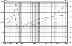
measure with a multimeter is pointless, you'll only get Re. read my sig, a proper impedance plot involves doing a frequency sweep of the driver and producing a graph of impedance vs. frequency. Look at a speaker data sheet to get the idea
I get you now! You are talking about this :
Attachments

The signal from an amp to a speaker is a POWER signal. Any crossover that handles such a signal has to operate at that power level. Electronic crossovers operate at line level, ie milli-watts. Be sure you understand that electronics including amplifies do not amplify, they carve a bigger copy out of their power supplies and hence their output is limited to the size of that power supply. The signal power output of any electronic device does not come from the signal input.
- Status
- This old topic is closed. If you want to reopen this topic, contact a moderator using the "Report Post" button.
- Home
- Loudspeakers
- Multi-Way
- Help needed - understanding crossovers