Impedance of Wharfedale mod

The woofer section with 2 drivers in parallel is about 5 ohms. The impedance rises higher in the single tweeter section. Below is the PCD7 curve. I did not make impedance measurement.Hi Keilau. As you said, it's all interesting. Are your speakers around 4 Ohms impedence?
Back with some info ...finally.
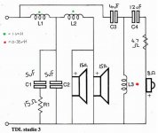
After starting this project nearly a year ago, with thte intention of just changing a few caps, it finally migrated into a full blown remodelling of the crossover on an external board and a move from 3rd order to 4th order.
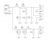
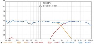
For somebody with virtually no experience, it has been a fairly hefty learning curve and I now realise why people said take measurements before you start, and you really need an LCR meter. I will make a recording of the speakers soon, but for now, I will attach diagrams of the original crossover, how it is now, and a current spl graph (I expect the values on my 4th order diagram may raise a few eyebrows, but it works with these speakers).
After starting this project nearly a year ago, with thte intention of just changing a few caps, it finally migrated into a full blown remodelling of the crossover on an external board and a move from 3rd order to 4th order.
For somebody with virtually no experience, it has been a fairly hefty learning curve and I now realise why people said take measurements before you start, and you really need an LCR meter. I will make a recording of the speakers soon, but for now, I will attach diagrams of the original crossover, how it is now, and a current spl graph (I expect the values on my 4th order diagram may raise a few eyebrows, but it works with these speakers).
Attachments
A cautionary note for first time users of any measuring system such as REW.
If you intent to create spl graphs by measuring your speakers - be aware that if you are recording your speakers in a room that is not acoustically perfect (and that's highly unlikely), speaker placement can dramatically affect the plot of the graph. I missed that bit when I was reading about configuring crossovers - and I spent a long time trying to work out why I was getting inconsistent measurements - it turned out that moving the speaker as little as 2cm could make a large difference (in my room anyway).
If you intent to create spl graphs by measuring your speakers - be aware that if you are recording your speakers in a room that is not acoustically perfect (and that's highly unlikely), speaker placement can dramatically affect the plot of the graph. I missed that bit when I was reading about configuring crossovers - and I spent a long time trying to work out why I was getting inconsistent measurements - it turned out that moving the speaker as little as 2cm could make a large difference (in my room anyway).
room effect on speaker measurement
You were able to measure the tweeter well above 10 KHz which seemed to indicate that you did the measurement in an extra large room.
The hardware addition for loudspeaker measurement is relatively inexpensive. I use the Dayton Audio EMM-6 Electret Calibrated Microphone
with a MXL-MICMATE XLR To USB Preamp. Total cost is about $100. USB cable, power amplifier are around the house. I use the ARTA software on a Windows 10 PC. For crossover mod/design support, it is a wonderful tool.
Your comment on loudspeaker measurement is well taken. Ideally, we would like to do it in an anechoic chamber, but few of us has access to one. Fortunately, the typical crossover region of 1-4 KHz is NOT the most sensitive to room acoustics. I have found good agreement between PCD software prediction and measured results in most cases in a reasonably sized room.A cautionary note for first time users of any measuring system such as REW.
If you intent to create spl graphs by measuring your speakers - be aware that if you are recording your speakers in a room that is not acoustically perfect (and that's highly unlikely), speaker placement can dramatically affect the plot of the graph. I missed that bit when I was reading about configuring crossovers - and I spent a long time trying to work out why I was getting inconsistent measurements - it turned out that moving the speaker as little as 2cm could make a large difference (in my room anyway).
You were able to measure the tweeter well above 10 KHz which seemed to indicate that you did the measurement in an extra large room.
The hardware addition for loudspeaker measurement is relatively inexpensive. I use the Dayton Audio EMM-6 Electret Calibrated Microphone
with a MXL-MICMATE XLR To USB Preamp. Total cost is about $100. USB cable, power amplifier are around the house. I use the ARTA software on a Windows 10 PC. For crossover mod/design support, it is a wonderful tool.
Hi Keilau - thanks for the reply. I used a behringer ECM8000 mic with REW. You might be surprised to learn my listening room is only 9' (2.7m) x 7' (2.1m) ...a bit of a nightmare for good reproduction of music but I have partially treated it with a bit of acoustic foam here and there. As you can guess, the speakers dominate the room but sound ok considering.
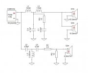
Please note that the 4th order diagram I uploaded does not truely work. I got it sounding pretty good but eventually realised there was a small phase issue between 2 and 2.5KHz. I believed that as a 4th order crossover, it would be fine, but I suspect because of the parallel woofers, there were issues (yes, I did unreverse the polarity on the tweaters). I have now reverted to a 3rd order crossover based on the original design from TDL but with a few minor tweaks - see diagram (This is still an ongoing project with further tweaks to come, but the values I have used are in the right region)
Attachments
Last edited:
Info for anyone experimenting with these speakers (and probably many others): Changing the resistor in the zobel network can drastically change the sound - not just changing the value but the type and make. The original wirewound was there for a reseason (apart from being cheap) ..the wirewound generally have an amount of inductance (amoungst other properties) and this will affect the amount of (unwanted) high frequencies perceived. I figured the cheapy 'coffin' white resistor would have the highest levels of inductance but it was not so.
Jantzen Superes had the highest of the resistors I measured with Ohmite gold being quite low and Mills being almost negligable - however, for this part of the crossover, the Jantzens were the most suitable and appeared to clean up the overall sound better than the others. The standard white ceramic wirewounds sat just above the Ohmites.
Jantzen Superes had the highest of the resistors I measured with Ohmite gold being quite low and Mills being almost negligable - however, for this part of the crossover, the Jantzens were the most suitable and appeared to clean up the overall sound better than the others. The standard white ceramic wirewounds sat just above the Ohmites.
That's a swell anecdote. But where are the measurements?Info for anyone experimenting with these speakers (and probably many others): Changing the resistor in the zobel network can drastically change the sound - not just changing the value but the type and make. The original wirewound was there for a reseason (apart from being cheap) ..the wirewound generally have an amount of inductance (amoungst other properties) and this will affect the amount of (unwanted) high frequencies perceived. I figured the cheapy 'coffin' white resistor would have the highest levels of inductance but it was not so.
But you can't claim to hear things you can't measure and then blame some physical property (like wire-wound inductance*) on the difference that would have to be big enough to measure.
B.
* usually very very tiny and does not compute except for a bat listener
I can claim to hear it because it exists. I didn't see a point in stating any measurements since it varies on the value of the resistor. I considered it useful advice for anyone experimenting with this kind of thing to take into account.
It's quite a negative comment you have made, bordering on rude - I'm being polite.
It's quite a negative comment you have made, bordering on rude - I'm being polite.
The point of doing measurements is that they can make credible claims of hearing sensitivity that appear to violate the laws of physics if not common sense too. Just post the numbers to support or doubt your claim.
Do you find it rude for me to suggest as much?
As for crossovers generally, it is misleading to see definitive-looking T/S parameter statements leading to passive crossover design. In reality, the driver parameters are scooting around with each frequency, back-EMF, motor movement, and little resonances. In that context, hardly worth fussing about a micro-henry here or there when using something as crude as a passive crossover.
B.
Last edited:
Yes, I do find your wording in a derisory manner rude. The only thing I might retract from my original statement is the word 'drastic' ..as it was drastic to my ears - but maybe not so much to another persons ears.
I agree that you would not expect such an audible difference when talking about a few micro henries ..but nonetheless, it was quite audibly different between the resistors used.
As I said, the Mills resistors were measuring at near to zero inductance. The Jantzen Superes measured 2.9 microhenries at 15 Ohms ...I didn't expect it to make as much difference either. (The Ohmite measured at just over 1.1 microhenries)
Also, I am obviously not 'blaming' wirewound resistors as being the sole factor in my observations since all 4 of the resistors I have mentioned are wirewound resistors.
Yes, I do find your wording in a derisory manner rude. The only thing I might retract from my original statement is the word 'drastic' ..as it was drastic to my ears - but maybe not so much to another persons ears.
I agree that you would not expect such an audible difference when talking about a few micro henries ..but nonetheless, it was quite audibly different between the resistors used.
As I said, the Mills resistors were measuring at near to zero inductance. The Jantzen Superes measured 2.9 microhenries at 15 Ohms ...I didn't expect it to make as much difference either. (The Ohmite measured at just over 1.1 microhenries)
Looks like there's nothing I could possibly comment that Thetall would not consider ridicule.
So anybody can do the math (OK, let the website do the math, you do the thinking):
Inductive Reactance Calculator • 66pacific.com
If that doesn't put a stop to the discussion of wire-wound inductance, then nothing ever will.*
B.
* OK, the discussion just might resume when we start using crossovers for drivers with 1 Ohm resistance instead of 4 or 8 Ohms
All 4 resistors mentioned are wire-wound ..there is obviosly something else at play other than just simply being wire-wound.
Have you tried swapping out a ceramic resistor from a zobel and replacing it with a wirewound of near zero inductance, or a metal oxide or film resistor? If you have, and could not hear a difference, then yes, our conversation is pointless - but I was trying to help anyone venturing into experimenting for the first time and may not be aware of the effect.
Have you tried swapping out a ceramic resistor from a zobel and replacing it with a wirewound of near zero inductance, or a metal oxide or film resistor? If you have, and could not hear a difference, then yes, our conversation is pointless - but I was trying to help anyone venturing into experimenting for the first time and may not be aware of the effect.
...Have you tried swapping out a ceramic resistor from a zobel and replacing it with a wirewound of near zero inductance, or a metal oxide or film resistor? If you have, and could not hear a difference, then yes, our conversation is pointless - but I was trying to help anyone venturing into experimenting for the first time and may not be aware of the effect.
Are you kidding? In 1968, using parts kindly supplied me by the Bell Labs stockroom*, I made my first electronic crossover. The plots are absolutely true to the design and permanently that way, hard to measure distortion, and perfect in all the textbook ways at 24dB/8ave. That is exactly what is fed to the drivers.
Ever plotted what is fed to your drivers?
B.
* no, not stealing, Bell Labs encouraged the scientists to explore any R&D they pleased
No, I wasn't kidding - I was simply asking a question that you didn't answer, but instead, asked a question that had nothing to do with the topic being discussed.
Anyway, the project continues and I'm learning all the time, especially since reading AllenB's crossover design thread - very interesting. One thing I noted was the influence of the baffle and having been only aware of different baffle designs previously, was surprised to discover how much influence they have after carrying out a few experiments on the Studio 3's. I was surprised to find that the design of the 3's baffle did not lead to a smooth response and have been experimenting with a few modifications.
More to follow in the coming weeks
-----------------------------------------------------------
Watch out watch out ...there be trolls about
- Home
- Loudspeakers
- Multi-Way
- TDL Studio 3 crossover upgrade is better and yet worse as well