Yes. We've all had such experiences, for sure.
Maybe we should rate our systems according to how far away you have to be in order to be "fooled".*
But even as stupid and synthetic a sound as your cellphone ringer.... would you ever mistake your cellphone ringing in your music room for a recording of it played on your fancy speakers? Maybe, if you were down the hall or across the street.
B.
*I'm working on a text comparing the down-the-hall audio test to the visual knothole test
I have picked up my phone several times thinking it rang when it was actually on a cd I was playing in the same room.
What are you referring to? It would depend on what aspect, for example it could have a linear frequency response (not likely) But it wouldn't be a linear speaker, there's no such thing, that's why I ask.back to distortion... how can a driver/loudspeaker having high harmonic distortion still be considered linear?
What about crossover distortion?unless there some form of exceptional case
that's why it's expressed as a percentage.
.. as in amplifiers.What about crossover distortion?
It has been known for a long time that lower order crossovers sound better, whether it is due to distortion levels or not, I have no idea. But doesn’t DAC have pretty high order filters?
Most measurements focus on forced response aspects of a system which is fine, but often ignored is the fact that our total experience is a combination of forced response and natural response.
Most measurements focus on forced response aspects of a system which is fine, but often ignored is the fact that our total experience is a combination of forced response and natural response.
Good way to get the thread going again by stirring up a bit of controversy.It has been known for a long time that lower order crossovers sound better, whether it is due to distortion levels or not, I have no idea.

Your sweeping claim makes it sound as if this a generally held belief and the debate has been settled but nothing could be further from the truth. Since the thread has gone dead, I'll bite.
If you constrain yourself entirely to the electrical domain and sum the responses of the filter sections electrically then yes of course, a lower order crossover is better, with the ultimate expression of that being the perfect phase perfect transient response of a summed 1st order low pass and high pass filter.
However crossovers don't just work in the electrical domain, they also work in the driver and acoustic domains, which adds extra dimensions of complexity to the problem.
In this scenario a low order filter is certainly a possible choice, but it's not the obviously correct or best choice in most cases. There are many tradeoffs that have to be balanced against each other. I'm sure you know this of course.
This thread is about distortion so the obvious trade off of low order filters is pushing drivers too hard outside their optimal frequency ranges, especially tweeters.
People sometimes forget that with a 1st order electrical filter on a tweeter the excursion still keeps increasing below the crossover frequency until you reach the resonance of the driver - not good!
It takes a 2nd order filter just to keep the excursion constant below the crossover frequency until the resonance of the driver and a 3rd order filter at minimum to reduce the excursion before the resonance - this applies even if you have an impedance conjugate for the tweeters resonance.
Ribbon tweeters are generally unusable with filters less than 3rd order as well due to their reduced low frequency capabilities. So a low order filter (in a good design) is off the table if you're using a small ribbon tweeter.
On the other side, you need a pretty amazing midbass driver to use a 1st order filter without cone breakup resonances above the crossover frequency clearly and obviously showing up in the resultant response.
As a rule of thumb there are two octaves of driver overlap required for a 4th order filter, four octaves of overlap for a 2nd order filter, and a staggering 8 octaves of clean driver overlap required for a 1st order crossover.
This is based on the number of octaves it takes for each driver to be approximately 20dB down - which is the point below which it doesn't contribute significantly to the summed response.
(Easily visualised by overlaying a normal phase and reverse phase summed response and seeing where the responses start to diverge from each other)
Putting aside the issues of power handling and distortion, getting drivers with this amount of clean overlap is almost but not quite impossible.
The reality is that most designs that use low order filters (1st and usually 2nd) do not have sufficient clean driver overlap and accept the compromise of the drivers out of band responses including cone break up and fundamental resonances appearing in the summed result.
A particular challenge with a 1st order filter is that a 1st order electrical filter doesn't usually mean a 1st order acoustic response - unless the drivers have a massive amount of flat overlap region that is very atypical.
With a higher order acoustic target you can get some of the slope from the drivers natural roll off and some from a lower order filter and meet your target, but with a 1st order acoustic target the drivers will typically already roll off more than this (mechanical rolloff of drivers is 2nd order at the bottom end and often at the top as well) making it impossible to actually achieve a 1st order acoustic crossover, at least using a passive network where you can only attenuate.
So I'd suggest that the vast majority of "1st order" crossover systems are nothing of the sort acoustically - they'll be at least 2nd order possibly 3rd once the driver responses are taken into account.
Lets assume for a moment that we create an actual 1st order acoustic response, either by using exceptionally wide band drivers, or an active crossover.
You then have the issue of the polar response. A 1st order crossover being odd order will sum with the drivers at 90 degrees. Looks good on paper - flat on axis response, flat power response.
But that ignores the fact that there will be a "hot spot" on the vertical lobe at the crossover frequency that is up to 3dB above flat, and because it's a low order filter that 3dB hump will be over a wide frequency range (a couple of octaves) so will be very, very obvious and audible coloration as soon as you go off the vertical axis a bit.
Going off the vertical axis the other way will cause a large dip over a wide frequency range, which is also undesirable.
Even on the horizontal plane things are worse than they would be with a higher order filter - with such a low order the larger driver of the two will be contributing significant output to very high frequencies which means the horizontal off axis response will be far from ideal as well.
If you are trying to transition from a cone driver to a constant directivity driver you will also get poor results because the lower frequency driver which is still becoming more directional at high frequencies has too much contribution to the output.
In short, a true acoustic 1st order, time aligned (summing at 90 degrees) 2 way system with non-coincident drivers is a bit of a directivity and polar response nightmare. The reality is that systems with 1st order electrical filters that sound good are going to be acoustically 2nd or possibly 3rd order, and are unlikely to be summing at 90 degrees either.
You could solve the polar response problem of a 1st order crossover by using a coaxial driver (in fact that solves the polar response problems of any crossover order) but you're still left with trying to achieve a huge overlap region. A coaxial 1st order system is more likely to be a success but still difficult.
So what are the benefit of higher orders and in particular even orders ?
The obvious benefit of higher orders is that less driver overlap is needed, and it becomes possible to heavily attenuate the response of a driver outside it's optimal frequency range.
This is the major and main benefit IMO. There are a lot of drivers out there that sound fantastic within their usable frequency range but fall apart in one way or another outside that range, whether it be cone breakup at the top end, distortion at the bottom end etc. With high order filters you can optimise the results of such drivers to get the best out of them.
The polar response of a speaker with a lower order filter can be dramatically improved with a higher order filter, especially if the correct crossover frequency is chosen.
If you are trying to cross a cone driver and a constant directivity tweeter the ideal place to cross them over is where their directivity matches. But if you do this with a very low order filter the end result is still not good because the large driver has too much contribution to the summed response above the crossover frequency where it is starting to beam.
As long as the directivity matches at the crossover frequency, the higher the order the filter the better up to a point, from the perspective of the polar response.
In the vertical plane an even order acoustic crossover can allow for phase tracking and in-phase summing on axis.
The big advantage of this is that you get the minimum shift in summed response as you go off the vertical axis because you need a phase shift error of at least 120 degrees either way before you start getting destructive cancellation between the drivers, and you can be up to about 45 degrees off with little effect on the summed response.
You also don't get any off axis "hot spot" - the (hopefully flat) on axis response is the highest response you'll see - off axis you'll only ever get dips which are much more benign sounding than peaks.
If you start with a phase shift of 90 degrees you not only have a 3dB hot spot off the vertical axis, but you only have to go about 30 degrees in phase off axis in the other direction before you start getting destructive interference between the drivers - and that assumes the drivers have a smooth response.
Real drivers have lumpy responses especially at their frequency limits, which means they also have lumpy phase responses. If both drivers are nominally summing in phase, then any phase response deviations from that nominal resulting from frequency response lumpiness will have minimal effect on the summing of the drivers, and statistically their individual bumps through the crossover region will tend to average out resulting in a smoother summed response than either of their individual responses.
However if they are summing with a nominal 90 degree phase offset this is not the case. A bump in response of one driver can easily add an extra 30 degrees of phase shift and push you towards destructive interference - so you can get narrow slices of frequency range in the crossover region where the drivers are actually destructively interfering with each other even on axis. This doesn't lead to good integration between the drivers.
IMO in-phase summing with phase tracking provides the best integration between drivers all else being equal, so on those and polar response grounds I would now tend to avoid odd order acoustic crossovers, although I have used them in the past.
A higher order filter reduces the bandwidth over which the response changes as you go off the vertical axis - this has the subjective result of the response not changing nearly as much off the vertical axis as it would with a lower order filter where destructive interference can occur over a very wide frequency range.
Another big advantage of higher order crossovers is "more degrees of freedom" to shape the response without adding additional components beyond what the filter itself calls for.
You don't have to stick with a classic electrical textbook response such as Linkwitz Riley or Butterworth, in fact if that is your acoustic target then the electrical target almost certainly won't be, and may not even be the same order.
A good example of this extra freedom to shape the response is the 4th order crossover I recently designed from scratch (I think I posted it earlier in this thread) where I wanted a target 4th order linkwitz riley acoustic response.
Because the drivers have a large amount of overlap I ended up using a 4th order electrical filter to do so, but they aren't anywhere near linkwitz riley electrically. One is much closer to a butterworth.
Both drivers have a significant dip in response at about 3Khz, but rather than adding additional components to correct this I ended up choosing 3Khz as the crossover frequency, (for that and other reasons) which gave me a great deal of freedom to shape the response in this frequency range.
By manually adjusting the coefficient of both filters in the sim away from their LR starting point I was able to achieve an almost perfect LR acoustic response with no additional components.
When you use a low order filter you have very little scope to shape the response to compensate for driver response errors without adding additional components - and you then end up with the same component count of a higher order filter anyway, so why not just make it a higher order filter and use those extra coefficients to shape the response ?
So what are the disadvantages of a high order filter ?
One disadvantage is that if you cross over at a frequency where your drivers have very dissimilar directivity you'll get a poor polar response and poor integration, and using a lower order filter can paper over this somewhat by spreading the directivity discontinuity over a wider frequency range. But it is only papering over the problem.
If you are able to match the directivity of the drivers at the desired crossover frequency (for example cone driver to constant directivity driver) a higher order crossover is actually beneficial to achieving the best polar response and integration between them.
The main disadvantage of a high order filter though is the ringing that it introduces at the crossover frequency. The higher the order the more it rings, and of the classic minimum phase filter topologies only the 1st order doesn't ring.
So if the drivers were perfect the ringing of the crossover would be undesirable. However you have to weigh up any potential ringing of the crossover against resonances of the drivers themselves.
A lower order crossover may ring less at the crossover frequency, but if it lets a lot more high frequency cone breakup resonances (which are arguably more objectionable) through, and perhaps buzzy distorted tweeter fundamental resonances, the end result can actually be a lot worse than just using the higher order filter.
Then add in increased distortion, worse polar response, and most likely, a less flat frequency response, and that slightly reduced ringing at the crossover frequency has come at a big cost.
In my opinion the ringing of a crossover should be treated on equal footing with any driver resonances to keep it in context - look at the CSD of the total summed response and see how the crossover resonance compares in severity to the cone breakup resonances... if you can greatly reduce audible cone breakup resonances at the expense of slightly more ringing at the crossover frequency (but still considerably less than the driver resonances that remain) then I'd say that's a good tradeoff. You also have the possibility of using linear phase filters to improve matters while still achieving higher order slopes.
Of course you don't want to make the filters any steeper than necessary, because you are then making the ringing at the crossover frequency even worse for little gain in reducing out of band response of the drivers.
For this reason I don't think there's any reason to go beyond 4th order for crossovers except in exceptional circumstances, and even then I would question the choice of drivers - in most cases I think 5th order and higher is beyond the point of diminishing returns.
If you stick to wanting in-phase summing, which IMO is desirable, that basically leaves you with 2nd and 4th order acoustic crossover responses being optimal for most situations.
Last edited:
Crossover distortion in amplifiers is a small non-linearity (with regard to full output) with a potentially large effect, for a few reasons. Its percentage doesn't rise gradually with level, is high with regard to low level signals, and has a wide range of higher order non-linear distortion. For these reasons I feel that expressing it as a percentage is pointless.the greater the linearity the less the harmonic distortion is, unless there some form of exceptional case that someone can show me that's how it works that's why it's expressed as a percentage.
Attachments
Good way to get the thread going again by stirring up a bit of controversy.
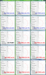
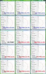
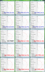
Thanks a good write up there, below visuals for vertical summing using free XDir will support the written words, spacing in all examples is a same relative low 1/4 wave length so if real spacing is larger it gets worse and if using coxial it will improve to a perfect polar in XO region.
First is BW1, second Harsch, third LR2, forth LR4, fifth LR8, and sith LR16
Attachments
-
 BW1 Q-wave WT_plus_procent_numbers.png519.4 KB · Views: 307
 -
 HARSCH (75Hz) Q-wave WT_plus_procent_numbers.png518.3 KB · Views: 307
 -
 LR2 Q-wave WT_plus_procent_numbers.png518.4 KB · Views: 292
 -
 LR4 Q-wave WT_plus_procent_numbers.PNG516.7 KB · Views: 278
 -
 LR8 Q-wave WT_plus_procent_numbers.PNG514.2 KB · Views: 74
 -
 LR16 Q-wave WT_plus_procent_numbers.PNG512.9 KB · Views: 80
It has been known for a long time that lower order crossovers sound better, whether it is due to distortion levels or not, I have no idea. But doesn’t DAC have pretty high order filters?
Most measurements focus on forced response aspects of a system which is fine, but often ignored is the fact that our total experience is a combination of forced response and natural response.
Yes DAC have high order filters and some of them can have filters that on paper looks like a mess, guess that's one reason we want own reproduce DAC and system to dynamical support all the various track material sample rates they are mixed for.
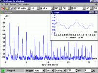
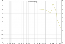
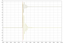
But also good old analog looks can distort into those areas, below is a previous generation B&W tweeter response measured at stereophile site that is translated here to a impulse response to se how that looks isolated on its own.
Think if measurement chain support it and a DSP is used running up at 96kHz or higher it should be possible system wise to correct for some of those high order ringing.
Attachments
Drivers should really be designed for better behavior near below and above the breakup region, I would probably never use a driver with a strong breakup mode. Sometimes I will try to tame it, but really, if driver manufacturers take greater care in the design process, basically there would be no need to redesign for a very long time.
I have tested some crossovers, and basically I ended up with simple series crossover. Parallel crossovers just produced sound that did not feel contiguous when the same subject plays across the crossovers. But I have not tested FIR filter based linear phase crossovers yet, but even if I do, I would probably go for the lowest order practical starting from first order. The low frequency cutoff order of the drivers are a different story, it is necessary to ensure that at maximum expected playback levels will not push the drivers beyond Xmax. I once added a tweeter to extend the high frequency up to near 40KHz, and had to increase the xo point to 10KHz even though the bandwidth went to as low as 1KHz.
Just last week while attending a B&K seminar, a few of us entered into a discussion as to why Sony requires frequency extension up to 40KHz to gain an HD sound certificate, it suddenly dawned on me that while I believed that phase was an important aspect, beyond the 20Hz and 20KHz extremes, it could be possible that although we cannot identify the sound when played back through earbuds during tests, it seems that we still feel the sound if it is radiated freely. It would probably be interesting to do some tests in a large Anechoic room to verify this. Recall the incident when US embassy persons were getting sick in Cuba and the speculation was that they were under subsonic sound attack.
DBMandrake wrote:
The main disadvantage of a high order filter though is the ringing that it introduces at the crossover frequency. The higher the order the more it rings, and of the classic minimum phase filter topologies only the 1st order doesn't ring.
This is new to me, please tell more about ringing! How does it sound? How does it show up in measurements? My guess is that this is some interference. How can we test it, playing sine at Fxo?
Another question, You didn't discuss phase rotation differences. Many people think that LR4 sounds worse than LR2 because of that. I have found in my dsp-speakers that LR2 sounds more natural (musical) despite of making them measure equally as per spl/F
Last edited:
Thanks for posting that, it's great to see it fully visualised.Thanks a good write up there, below visuals for vertical summing using free XDir will support the written words, spacing in all examples is a same relative low 1/4 wave length so if real spacing is larger it gets worse and if using coxial it will improve to a perfect polar in XO region.
First is BW1, second Harsch, third LR2, forth LR4, fifth LR8, and sith LR16
1/4 wavelength spacing between a midrange and tweeter is pretty low and hard to achieve unless you use small drivers and a rather low crossover frequency that I would not be happy using.
I would suggest 1/2 to 1 wavelength would be more typical of real designs for midrange to tweeter spacing.
Even at 1/4 wavelength, the destructive interference in the vertical polar response from the 1st order filter is pretty bad at high frequencies, and non existent on the higher orders.
My speakers have unusually wide centre to centre driver spacing of 1.75 wavelengths at 3Khz so would be even more sensitive to filter order off the vertical axis.
I'll have to download that app and try some simulations at 1.75 wavelengths. I'm sure it won't look pretty, even with 4th order!
(Edit: how are you entering the filter type into the app ? Or are you calculating the phase and amplitude of a given filter response elsewhere and manually entering it ?)
The centre to centre driver spacing is 20cm purely due to the large size of the drivers. (8" full range with a somewhat bulky frame and a ribbon tweeter with a largish face plate) I could have reduced that by maybe 3cm at most, except there is a front to back panel strut between the midbass and tweeter that I don't want to remove that was there since before the speaker even had a tweeter in the cabinet. (And another one just below the midbass driver)
I don't think reducing it by 3cm would make a significant improvement to the relatively large spacing, but the removal of a strut and weakening of the panel by cutting the holes much closer together would have a detrimental effect on the cabinet's structural performance. (There's those pesky compromises and trade-offs to be weighed up again.
)I've tried different orders filters with these full range drivers with various tweeters over the years, including 2nd, 3rd and 4th. I used it with a 3rd order filter for years with reasonable results but I think the 4th order sounds better and absolutely measures better.
It could well be that part of the reason I'm favouring the 4th order crossover with these speakers is that it helps to minimise the effects of a relatively wide driver spacing and make it a lot more workable. Despite the large driver spacing the subjective vertical off axis response is surprisingly good - I notice the top end off axis roll-off of the ribbon tweeter more than I notice any holes in the presence region near the crossover frequency.
Last edited:
Good question. Actually, you can't hear ringing (FR plot) any more than you can hear beaming (polar plot). Both exist as visual aberrations on plots.DBMandrake wrote:
The main disadvantage of a high order filter though is the ringing that it introduces at the crossover frequency. The higher the order the more it rings, and of the classic minimum phase filter topologies only the 1st order doesn't ring.
This is new to me, please tell more about ringing! How does it sound? How does it show up in measurements? My guess is that this is some interference. How can we test it, playing sine at Fxo?
You can explore these phenomena by playing with your audio oscillator and by walking around speakers, respectively. But that's not the same as hearing them like you'd hear third-harmonic distortion.
B.
- Home
- Loudspeakers
- Multi-Way
- Who makes the lowest distortion speaker drivers