May be available this month:
Celestion Announces NAMM 2019 Debut of Axi2050 Axiperiodic Driver | Live Design
In spite of the great fanfare and proclamation, this was launched as band-aid:
An externally hosted image should be here but it was not working when we last tested it.
Last edited:
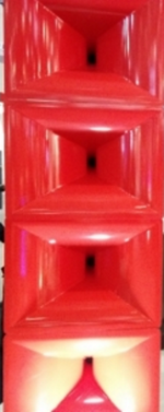
Apparently, the Red Horn shown earlier in this thread is a custom design, perhaps with input from Bjørn Kolbrek.
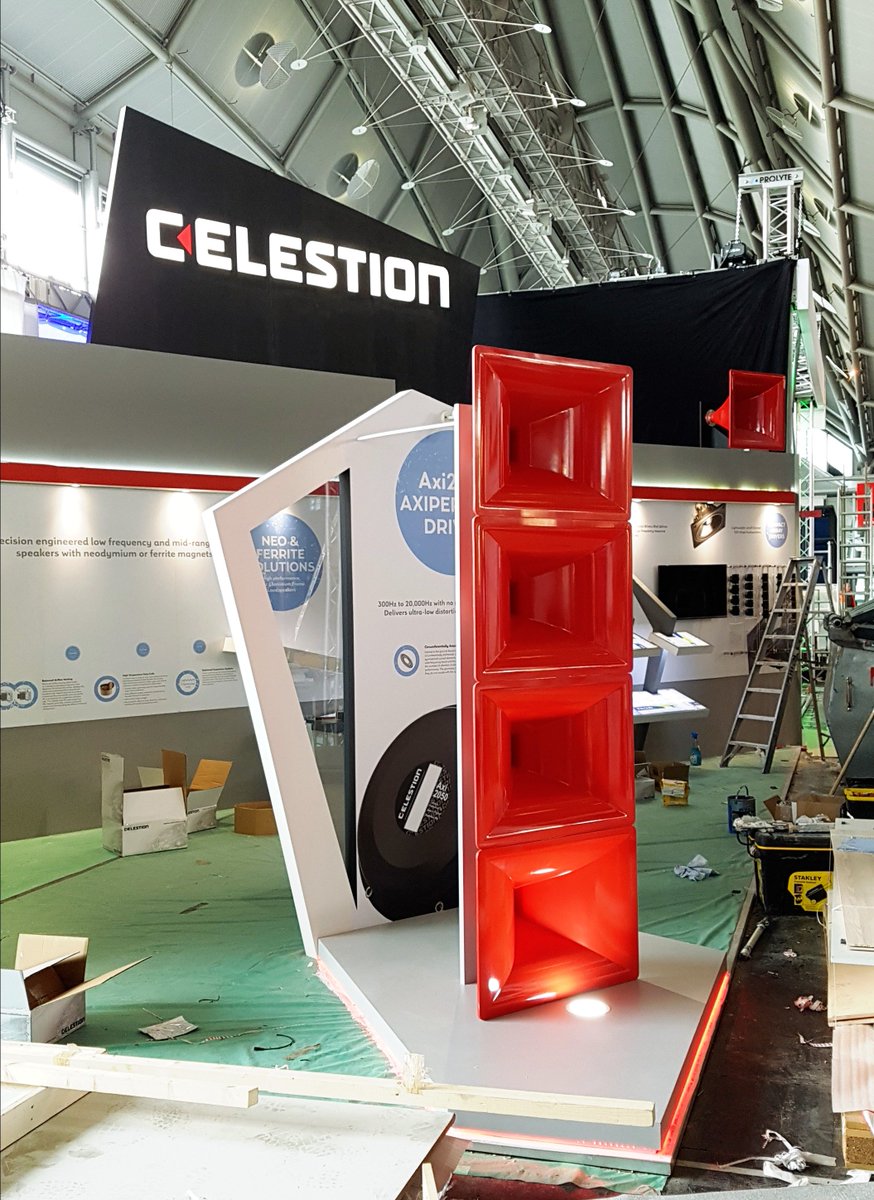
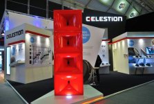
The Red Horns have been exhibited with the Axi2050 (instead of the SEOS) and were supposed to be used for the NAMM as well.
These are made by an UK manufacturer of bespoke Glass Fibre Reinforced Plastics (GRP) products.
The Red Horns have been exhibited with the Axi2050 (instead of the SEOS) and were supposed to be used for the NAMM as well.
These are made by an UK manufacturer of bespoke Glass Fibre Reinforced Plastics (GRP) products.

...and with vertical to horizontal transition/slot.
Such transitions seem to be en vogue (again).
Even some audiophool loudspeakers have 'em...
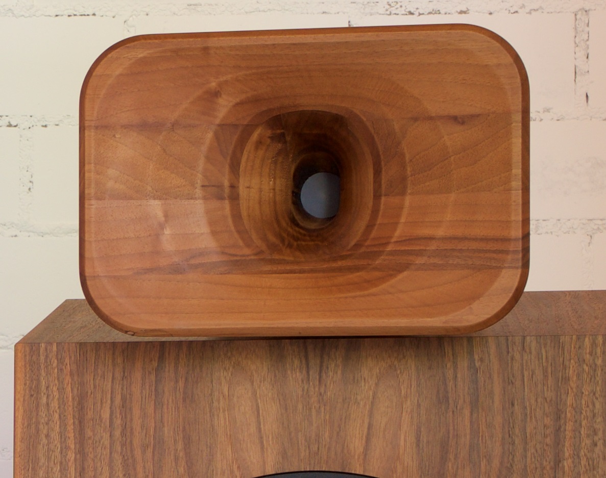
I don't think the red horns are similar to Manta Ray horns, if that's what you suggested, silversprout.
The transition is very sharp and the first section looks really narrow, i'm perhaps wrong but i still vote for a mantaray profile.

PS : the white particles on my red mantaray photo is marine snow

Marine snow - Wikipedia
Last edited:
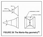
If you consider every horn with a vertical slot a Mantaray horn, I would agree. However, that would be an oversimplification. Moreover, a CAD drawing of the exterior can be misleading. Judging from the images, the actual horns are clearly different in my opinion.
Mantaray Horns
The Mantaray is a Constant Directivity (CD) design horn that keeps the dispersion angle constant for all frequencies, and reduces the beaming inherent in many loudspeakers. It was designed by Clifford A. Henrickson and Mark S. Ureda of Altec Lansing using the principles first established by Don Keele of Electro-Voice (later JBL).
The Mantaray separates desired vertical coverage patterns from horizontal, making it possible to design horns for a variety of coverage patterns. The Mantaray shape starts with a vertically oriented, narrow and sharp-edged JBL-style diffraction horn leading into a conical waveguide (earliest designs) or a square or rectangular horn with four planar sides. For midrange beaming control, the outer mouth was expanded further with a short, flared flange in the Keele style, or with added planar sides of a greater flare angle. Low frequency efficiency was not as pronounced as the constant directivity design. Unlike previous designs, the apparent apex, the focal point of pattern dispersion, was not the same for every frequency, making for an ellipsoidal wavefront rather than spherical. Because of this, the Mantaray could only be arrayed satisfactorily in one plane. Its abrupt breaks in flare rate caused diffraction, reflection and distortion components.
Most popular Constant Directivity horns suffer from non-spherical wavefronts, limitations in arrayability, distortion at high sound pressure levels as well as reflections and distortions related to the transition from diffraction slot to secondary horn. They tend toward a narrowing of dispersion pattern at the higher frequencies whose wavelengths approach the width of the throat or the width of the diffraction slot.
Not very compelling, I would say.
If you look towards the throat, the slot in the red horns appears to be a little wider and the edges seem smoother.
I think the description below (by Bjørn Kolbrek) is more appropriate.
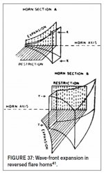
REVERSED FLARE HORNS
The reversed flare horn can be considered to be a “soft diffraction horn,” contrary to Manta-Ray horns and other modern constant directivity designs that rely on hard diffraction for directivity control.
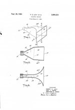
This class of horns was patented for directivity control by Sidney E. Levy and Abraham B. Cohen at University Loudspeakers in the early 1950s.
The same geometry appeared in many Western Electric horns back in the early 1920s, but the purpose does not seem to be that of directivity control.
The principle for a horn with good horizontal dispersion is illustrated in Fig. 37.
The wave is allowed to expand in the vertical direction only, then the direction of expansion is changed.
The wave-front expansion is restricted vertically, and is released horizontally. The result is that the horizontal pressure that builds up in the first part of the horn causes the wave-front to expand more as it reaches the second part. That it is restricted in the vertical plane helps further. Because the wave-front expansion is to be exponential all the way, the discontinuity at the flare reversal point (where the expansion changes direction) is small.
IN ADDITION, THE CHANGE OF CURVATURE AT THE FLARE REVERSAL POINT IS MADE SMOOTHER IN PRACTICAL HORNS THAN WHAT IS SHOWN IN THE FIGURE.
Mantaray Horns
The Mantaray is a Constant Directivity (CD) design horn that keeps the dispersion angle constant for all frequencies, and reduces the beaming inherent in many loudspeakers. It was designed by Clifford A. Henrickson and Mark S. Ureda of Altec Lansing using the principles first established by Don Keele of Electro-Voice (later JBL).
The Mantaray separates desired vertical coverage patterns from horizontal, making it possible to design horns for a variety of coverage patterns. The Mantaray shape starts with a vertically oriented, narrow and sharp-edged JBL-style diffraction horn leading into a conical waveguide (earliest designs) or a square or rectangular horn with four planar sides. For midrange beaming control, the outer mouth was expanded further with a short, flared flange in the Keele style, or with added planar sides of a greater flare angle. Low frequency efficiency was not as pronounced as the constant directivity design. Unlike previous designs, the apparent apex, the focal point of pattern dispersion, was not the same for every frequency, making for an ellipsoidal wavefront rather than spherical. Because of this, the Mantaray could only be arrayed satisfactorily in one plane. Its abrupt breaks in flare rate caused diffraction, reflection and distortion components.
Most popular Constant Directivity horns suffer from non-spherical wavefronts, limitations in arrayability, distortion at high sound pressure levels as well as reflections and distortions related to the transition from diffraction slot to secondary horn. They tend toward a narrowing of dispersion pattern at the higher frequencies whose wavelengths approach the width of the throat or the width of the diffraction slot.
Not very compelling, I would say.
If you look towards the throat, the slot in the red horns appears to be a little wider and the edges seem smoother.
I think the description below (by Bjørn Kolbrek) is more appropriate.
REVERSED FLARE HORNS
The reversed flare horn can be considered to be a “soft diffraction horn,” contrary to Manta-Ray horns and other modern constant directivity designs that rely on hard diffraction for directivity control.
This class of horns was patented for directivity control by Sidney E. Levy and Abraham B. Cohen at University Loudspeakers in the early 1950s.
The same geometry appeared in many Western Electric horns back in the early 1920s, but the purpose does not seem to be that of directivity control.
The principle for a horn with good horizontal dispersion is illustrated in Fig. 37.
The wave is allowed to expand in the vertical direction only, then the direction of expansion is changed.
The wave-front expansion is restricted vertically, and is released horizontally. The result is that the horizontal pressure that builds up in the first part of the horn causes the wave-front to expand more as it reaches the second part. That it is restricted in the vertical plane helps further. Because the wave-front expansion is to be exponential all the way, the discontinuity at the flare reversal point (where the expansion changes direction) is small.
IN ADDITION, THE CHANGE OF CURVATURE AT THE FLARE REVERSAL POINT IS MADE SMOOTHER IN PRACTICAL HORNS THAN WHAT IS SHOWN IN THE FIGURE.
Attachments
Last edited:
On the marine snow, let's hope it'll remain 'mostly organic'
As in real life there is some things that have to be considered more than others and it is a matter of a choice, the marine snow is pushing the concept to the exteme limit, what you have to eat (deisgn) is highly dependent of your specie (application).
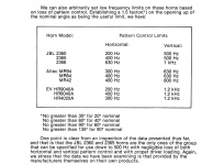
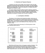
I will be curious to know the lowest recommended loading frequency of that CD red horn.
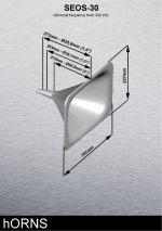
Considering the Red Horn's length (depth), the mouth circumference, as well as the parameters of the previously used SEOS-30, I would guesstimate the Red Horn loads the driver from 300-350Hz.
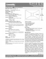
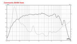
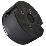
As mentioned before, I think the Red Horns are more similar to Community's SH-494 than to most widely known medium/large format horns.
It's no coincidence the SH-494 is a hidden gem among BMS coaxial users.
As mentioned before, I think the Red Horns are more similar to Community's SH-494 than to most widely known medium/large format horns.
It's no coincidence the SH-494 is a hidden gem among BMS coaxial users.
Attachments

Last edited:
Quote from:
Loudspeakers: For Music Recording and Reproduction, Second Edition, by Philip Newell and Keith Holland (2019).
"A PhD thesis by Oclee-Brown introduced an approach where, rather than attempting to produce the
constant velocity profile of a rigid piston, the target was to produce a velocity profile which does not
excite the acoustic modes. This approach was adopted by the Celestion team which, after exploring a
number of different geometries, produced an annular diaphragm geometry with an axi-periodic pattern
embossed in it (for the Axi2050 compression driver). This pattern allows the diaphragm to hinge at both
the coil and the diaphragm edges, resulting in a velocity which is maximum at the coil and progressively
decreases to the edges (becoming zero at the internal and external clamping diameters). Such a geometry
has a number of benefits. Firstly, the diaphragm can be designed so that the first radiating mode is
very high for the driver size. Secondly, the material may be thinner than the usual material for the size,
since the features on the diaphragm are small. Thirdly, the diaphragm provides a very linear restoring
force, thus allowing lower distortion at high levels of mid frequencies.
Another solution is the adoption of ‘meandering’ phasing plug slots. Instead of the usual radial or
annular slots for connecting the compression chamber to the acoustic exit, these designs employ slots
arranged at an angle to a radius, which results in some ‘averaging’ of the effects of the modal behaviour
of the compression cavity/diaphragm system on the acoustical output, and hence a smoother frequency
response at high frequencies. This idea has been implemented in a number of JBL compression drivers
based on annular polymer diaphragms, such as the models 2423K, D2415K, and D2430K.
Dual-diaphragm compression drivers are also now being developed. These drivers essentially consist
of two annular compression drivers mounted face-to-face in a push-push arrangement with a common
acoustic exit through the centre of one of them. The advantage here is that there are effectively two
drivers in a single compact device with a common acoustical output, giving rise to increased power
handling, lower thermal compression, and lower non-linear distortion compared to the equivalent
single-diaphragm driver. Furthermore, the two, separate voice coils can be connected either in series or
in parallel for added system flexibility. This approach has been adopted in a range of JBL compression
drivers, which also incorporate the meandering slots mentioned above."
Last edited:
"number of different geometries, produced an annular diaphragm geometry with an axi-periodic pattern embossed in it
Is there any relationship with the Olsen duo-cone shape ?

Harry F. Olson was passionate about vibration in general. He has done a lot of research on (pistonic/vibrational behaviour of) membranes, diaphragms and plates > Chapter 2 and 3.
There are some similarities between the duo cone and the features on the Axi2050 diaphragm. Apart from this, a direct radiating paper cone and a metallic compression loaded diaphragm are very different.
I think the Japanese diaphragms mentioned earlier are more comparable.
There are some similarities between the duo cone and the features on the Axi2050 diaphragm. Apart from this, a direct radiating paper cone and a metallic compression loaded diaphragm are very different.
I think the Japanese diaphragms mentioned earlier are more comparable.
Considering the Red Horn's length (depth), the mouth circumference, as well as the parameters of the previously used SEOS-30, I would guesstimate the Red Horn loads the driver from 300-350Hz.
As mentioned before, I think the Red Horns are more similar to Community's SH-494 than to most widely known medium/large format horns.
It's no coincidence the SH-494 is a hidden gem among BMS coaxial users.
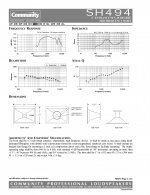
The SH-494 is described as an exponential horn (narrowing pattern) though and looks to have issues > 4 kHz in the data sheet. Midrange only?
The axi2050 is still listed as OEM only so may as well not exist though. My interest has declined somewhat due to this. Also getting a pair of auto tech SEOS-30 was ~600euro making the whole project a bit expensive.
Measurement data were obtained with the Community M200 Midrange driver, which drops like a rock past 4kHz.
Optimum crossover frequencies according to the M200 datasheet are 500Hz / 4kHz.
It's a highly regarded driver nonetheless.
Attached the response of an Eminence PSD3006 with the same horn. This is a mediocre driver though.
I took the SH-494 as an example of a different kind of diffraction horn.
I am convinced the smart guys at Celestion, with their combined know-how and the best tools at hand, are more than capable to ensure optimal performance of the Axi2050 with the Red Horn.
On the other hand, the time to market is extraordinary.
Attachments
Last edited:
Harry F. Olson was passionate about vibration in general. He has done a lot of research on (pistonic/vibrational behaviour of) membranes, diaphragms and plates > Chapter 2 and 3.
There are some similarities between the duo cone and the features on the Axi2050 diaphragm. Apart from this, a direct radiating paper cone and a metallic compression loaded diaphragm are very different.
I think the Japanese diaphragms mentioned earlier are more comparable.
He also said that the superiority of the horn loaded loudspeakers is induced by the fact that the motion of the membrane is controlled by the air instead of the peripheral suspension.
At 300 Hz, will the acoustical resistance of the red horn sufficient to control the mendrane motion or will they add a mesh grill on the driver exit in order to raise it ?
A (thin) mesh grille is visible on the published images of the driver. This is a necessity in some PA environments to prevent debris from penetrating the driver's inards.
No details of the Red Horn have been published yet, so we can only speculate about the performance of the Axi2050 with the horn.
Attachments
Last edited:
He also said that the superiority of the horn loaded loudspeakers is induced by the fact that the motion of the membrane is controlled by the air instead of the peripheral suspension.
Although this is true, it doesn't mean the suspension is unimportant. Even more so for wide bandwidth drivers like the Axi2050.
Last edited:
- Home
- Loudspeakers
- Multi-Way
- New Celestion "AxiPeriodic Driver"