OK, figured out a way to record the speaker doing a square wave sweep. Not too impressive if you've never seen a speaker attempt this before (the waveform normally looks NOTHING like a square wave), but this is what it looks like anyway.....
https://www.youtube.com/watch?v=Z-3blqulULw
(Is there a way to embed a YouTube video on this forum?)
https://www.youtube.com/watch?v=Z-3blqulULw
(Is there a way to embed a YouTube video on this forum?)
wow, those measurements look pretty good!
Crazy good actually! I love it!
I would love to see the impulse and an early waterfall plot (~3ms with 0.1 ms rise time). Not to criticize, just to learn. (and see what I'm missing by not choosing the Synergy myself)
And it would also be fun and educative to see an APL_TDA plot, made with the demo version of that software tool. But that would require another measurement session.
Great stuff, (as usual).

Bravo Bwaslo. And good look too ")
Surprised than this Tymphany compression driver beats the Faitals or B&C.
I defintly like the fact it's a passive design.
PS : for the germs : try for a month and every day in your food : fresh garlic (not heated), and fresh lemon juice drinked immerdiatly (without sugar). If you can : 1 hour of sleep more per night during this month. Not wifey approved but defintly good for the health to finish to cure a flue and stop post germs infections.
Last edited:
Hi Bill:
Great results! Makes we wish I had decided to drill my SEOS18s first rather than do wooden conical horns.
Can I ask
- what gating/smoothing/windowing you use on the measurements when designing the crossover? Results are varying considerably with my in-garage measurements so I might have to drag mine outside...
- In your house/target curve, how much and where do you depress the treble and or elevate the bass?
Thanks.
Jack
Thanks, everyone. I should mention that the crossover got a lot more expensive than the simple crossover I showed very early in this thread. Higher order in the midrange (to keep distortion down, but mostly to manage the polar region) and now I'm using two each of those huge ERSE dog-bone inductors (>$20 each) to minimize distortion and series resistance because the inductance got big and the woofers are 4 ohms. Probably one of them can be the smaller type, but I figured, "what's another $10?".
Wesayso,
Actually the impulse response of the speaker (without the FIR EQ) is only fair at best, because of the higher-order crossovers. The design priority was polar pattern and frequency response when placed near a wall (also, passive crossover linear phase is hard to do in a 90degree synergy horn!). Of course, with a miniDSP 2-wayHD doing FIR EQ, one can make the impulse of about any speaker look pretty nice, so I did that instead (I still think that is way less important than polar, though, and don't think linear phase is really necessary - though it's so cheap these days, why not, except for the digital phobic folks). The Synergy aspect is still an advantage, though, since the IR is about the same where ever you put the microphone, because of the almost-point-source behavior.
Last edited:
nc535,
I'm windowing at about 4msec when measuring in my cluttered basement, it's a Blackman-Harris window. I do the measurements unsmoothed, but then smooth them to 1/6th octave when designing the crossover in XSim. If you are using OmniMic, make sure you download the latest software (version 5), as it uses a much more effective sliding window beyond the chosen reflection gate. The previous versions were basically a frequency - weighted blend of short, medium and no window, but version 5 now actually weights the window continuously so that it is also weighted toward earlier time portions of the impulse response when it has to start letting reflections in. That seems to give a better match to outdoor results. Except down at bass frequencies, of course, where no such magic will help (near field is the way to go down there... but bass didn't involve the crossover, so that didn't matter much in this case). You can see, though, that I unfortunately didn't get the (simulated) directivity down to the 200Hz-300Hz once I got outside. I wasn't really expecting to -- the spaced woofers shouldn't be doing much down by those frequencies. That was a measurement or placement anomaly (lots of junk in the room).
I was going for it to start tipping down at about 1 or 2kHz, but ended up with it starting much lower as that worked out better for the midrange-woofer polar blending. Also, there is that big bump at 100Hz from the woofers in that small box and an interraction in the crossover. Since that's in the region where room modal effects play heck with the response anyway, I'm not too worried about it. Since I have the miniDSP in the loop anyway, I knocked down the 100Hz by a few dB and boosted below that to get some bass. along with some minor room EQ. The bass done that way sounds a lot better than it has any right to, given the rolloff before EQ and the climbing distortion down below 100Hz. I'm sure it would still sound better with subs, though!
- what gating/smoothing/windowing you use on the measurements when designing the crossover? Results are varying considerably with my in-garage measurements so I might have to drag mine outside...
I'm windowing at about 4msec when measuring in my cluttered basement, it's a Blackman-Harris window. I do the measurements unsmoothed, but then smooth them to 1/6th octave when designing the crossover in XSim. If you are using OmniMic, make sure you download the latest software (version 5), as it uses a much more effective sliding window beyond the chosen reflection gate. The previous versions were basically a frequency - weighted blend of short, medium and no window, but version 5 now actually weights the window continuously so that it is also weighted toward earlier time portions of the impulse response when it has to start letting reflections in. That seems to give a better match to outdoor results. Except down at bass frequencies, of course, where no such magic will help (near field is the way to go down there... but bass didn't involve the crossover, so that didn't matter much in this case). You can see, though, that I unfortunately didn't get the (simulated) directivity down to the 200Hz-300Hz once I got outside. I wasn't really expecting to -- the spaced woofers shouldn't be doing much down by those frequencies. That was a measurement or placement anomaly (lots of junk in the room).
- In your house/target curve, how much and where do you depress the treble and or elevate the bass?
I was going for it to start tipping down at about 1 or 2kHz, but ended up with it starting much lower as that worked out better for the midrange-woofer polar blending. Also, there is that big bump at 100Hz from the woofers in that small box and an interraction in the crossover. Since that's in the region where room modal effects play heck with the response anyway, I'm not too worried about it. Since I have the miniDSP in the loop anyway, I knocked down the 100Hz by a few dB and boosted below that to get some bass. along with some minor room EQ. The bass done that way sounds a lot better than it has any right to, given the rolloff before EQ and the climbing distortion down below 100Hz. I'm sure it would still sound better with subs, though!
Wesayso,
Actually the impulse response of the speaker (without the FIR EQ) is only fair at best, because of the higher-order crossovers. The design priority was polar pattern and frequency response when placed near a wall (also, passive crossover linear phase is hard to do in a 90degree synergy horn!). Of course, with a miniDSP 2-wayHD doing FIR EQ, one can make the impulse of about any speaker look pretty nice, so I did that instead (I still think that is way less important than polar, though, and don't think linear phase is really necessary - though it's so cheap these days, why not, except for the digital phobic folks). The Synergy aspect is still an advantage, though, since the IR is about the same where ever you put the microphone, because of the almost-point-source behavior.
I care about linear phase in the pass band (below about 1-2 kHz) to as low as I still have output and it gives "power" to the midrange that way. As long as the output is there. But it has to work at the listening spot and around it. A Synergy speaker can do that as, like you mentioned, the IR will be about the same if you move up/down left/right. But it's hard to do it and have it sound "natural" in a room. But definitely worth it to me for that "live" feel, especially on percussion. It's also great in movies. A frequency dependent window of about 5/6 cycles is my aim to have it as correct as I can get it. Overcorrect the phase down low and it sounds awkward. Get it right and your feet starts tapping. And you can feel notes on your eyelids.
. another form of synergy .I think you've seen this picture before, an APL_TDA plot taken at the listening position with both speakers playing:

That's a clear picture of what I aimed for, but neither side (left or right) is absolutely perfect by itself (below 100 Hz). On the left side I have a corner problem at ~70 Hz, I'm not trying to correct that phase swing. I bring down the (early) dip by a few dB's and let my other side array play a little louder to compensate. Down lower I do the same on the right side, this time because the left side needs less boost to get the SPL I want. Together they sum flat and have the phase mimic the FR curve when you look at it with a ~5/6 cycle frequency dependent window. (FR curve is tilted down, so is the phase)
Quite a different view from no FIR correction at all (still both speakers playing):

But more important, it sounds tighter, more like a real drum out in the room. I've played with lots of different window lengths, both longer and shorter. Longer windows did sound different, and only slightly correct at the listening spot. The shorter the frequency dependent window, the more "real" and natural the drum hits sounded. Or a pool shot, and many more sounds. But it also worked outside the sweet spot. I did a lot of digging trough the graphs to find the sweet spot, but simply forcing phase flat does not work i.m.h.o. Don't fix the room anomalies, only the direct sound, if you can find it. The spectrogram plot in REW can show you that, browsing trough time (the gating length) and looking what that does with phase and FR you can learn the room (at least what it does at the sweet spot). You'll see what that first wave front does, and where the room takes over. The bigger room effects can only be really fixed with traditional room treatment. Not by forcing phase in shape. The general curve can be adjusted. And it will solve more than one might think.
In REW wavelets:


With arrays, and Synergies should do the same, the IR is kept the same over a wide area.
The room being the biggest culprit of coarse. Fix what you can, accept the rest is my motto.
That's a clear picture of what I aimed for, but neither side (left or right) is absolutely perfect by itself (below 100 Hz). On the left side I have a corner problem at ~70 Hz, I'm not trying to correct that phase swing. I bring down the (early) dip by a few dB's and let my other side array play a little louder to compensate. Down lower I do the same on the right side, this time because the left side needs less boost to get the SPL I want. Together they sum flat and have the phase mimic the FR curve when you look at it with a ~5/6 cycle frequency dependent window. (FR curve is tilted down, so is the phase)
Quite a different view from no FIR correction at all (still both speakers playing):
But more important, it sounds tighter, more like a real drum out in the room. I've played with lots of different window lengths, both longer and shorter. Longer windows did sound different, and only slightly correct at the listening spot. The shorter the frequency dependent window, the more "real" and natural the drum hits sounded. Or a pool shot, and many more sounds. But it also worked outside the sweet spot. I did a lot of digging trough the graphs to find the sweet spot, but simply forcing phase flat does not work i.m.h.o. Don't fix the room anomalies, only the direct sound, if you can find it. The spectrogram plot in REW can show you that, browsing trough time (the gating length) and looking what that does with phase and FR you can learn the room (at least what it does at the sweet spot). You'll see what that first wave front does, and where the room takes over. The bigger room effects can only be really fixed with traditional room treatment. Not by forcing phase in shape. The general curve can be adjusted. And it will solve more than one might think.
In REW wavelets:
With arrays, and Synergies should do the same, the IR is kept the same over a wide area.
The room being the biggest culprit of coarse. Fix what you can, accept the rest is my motto
.
Last edited:
Thanks for the links and the nice plots, will have to dig into those a bit more. I've done the spectrograms before (the wavelets, last plots in your post) and probably should redo those and post them as well. I'm surprised the blue blobs on yours around 400 and 500Hz went away with FIR EQ, I would think those would be room reflections? (or maybe ceiling reflections and more constant over the room?)
That's not too hard with a Synergy horn (or other point sources), since all stays pretty much the same if you put the mic up close to the speaker. That's where I did the phase EQ from (maybe I should have done the YouTube square wave sweep from there, too?).
don't fix the room anomalies, only the direct sound, if you can find it.
That's not too hard with a Synergy horn (or other point sources), since all stays pretty much the same if you put the mic up close to the speaker. That's where I did the phase EQ from (maybe I should have done the YouTube square wave sweep from there, too?).
Try and simulate a speaker with a crossover at, say 200 Hz, look at the early waterfall plots from that virtual test, next linearize that crossover and look again. It clears up the waterfall way above that crossover point. BYRTT has posted graphs like that to illustrate it. It's what I see in my listening spot measurements.
More important, I hear more clarity. More songs sound right. More impact on notes.
Of coarse frequency response and polar response is important, but that should include what's happening over time. Hear and feel it...
More important, I hear more clarity. More songs sound right. More impact on notes.
Of coarse frequency response and polar response is important, but that should include what's happening over time. Hear and feel it...
Thanks for the links and the nice plots, will have to dig into those a bit more. I've done the spectrograms before (the wavelets, last plots in your post) and probably should redo those and post them as well. I'm surprised the blue blobs on yours around 400 and 500Hz went away with FIR EQ, I would think those would be room reflections? (or maybe ceiling reflections and more constant over the room?)
I never really did find the clue, only that it stayed pretty much the same, left to right over the listening area. So probably the ceiling, or the array length as I saw it in Halair's measurements at a different frequency and he has slightly shorter arrays. There's still some reflections (around 140 to 230 Hz) in the right channel but I made a promise not to put up any more damping panels
.That's not too hard with a Synergy horn (or other point sources), since all stays pretty much the same if you put the mic up close to the speaker. That's where I did the phase EQ from (maybe I should have done the YouTube square wave sweep from there, too?).
Yes, indeed! The phase will only be truly correct at that exact spot. Which is why I concentrate on what's happening at and around the sweet spot.
And why I picked arrays, and have a thing for the synergies. (maybe with array bass on top and below
)
Last edited:
I'm using two holes for the one midrange driver, each is 0.375 inches (0.95cm) in diameter. I drill them so the hole is bored at an angle (relative to the horn wall) so they come out closer to the tweeter throat. But I didn't use any frustrums (to make the design easier to repeat) so you could probably make the holes a little smaller if you frustrum.
The hole sizes, etc, will likely change if done at a different position or on a different horn, though. Make sure you HornResponse it and leave yourself a way to adjust the front volume in front of the driver.
Bill
Bill
The hole sizes, etc, will likely change if done at a different position or on a different horn, though. Make sure you HornResponse it and leave yourself a way to adjust the front volume in front of the driver.
Bill
Bill
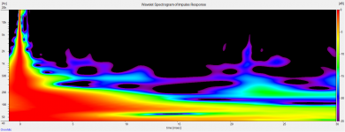
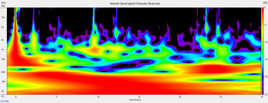
Here are some wavelet spectrograms, measured close in and near listening chair. (The EQ isn't set up for a sweet spot, as there are several regularly used seats and seats get moved around).
Don't know if these are comparable to WeSaySo's plots, I set for: 1 octave, response normalized, 25dB range. Different software, too.
Don't know if these are comparable to WeSaySo's plots, I set for: 1 octave, response normalized, 25dB range. Different software, too.
Attachments
How to do the horn modifications on a SEOS15 for SmallSyns
since there was a question about drilling holes (ports) for the midrange --
(from a writeup I did a while ago but didn't blog yet
Mods to the horn involves first moving the two tweeter mounting holes to get them away from the midrange that would otherwise block them; then cutting port holes for the midrange; then fabricating and attaching a mounting plate for the midrange and filling in some resulting volume. None of it is too hard, and I avoided making changes that couldn’t be specified and duplicated accurately enough on a shop bench. But it will take a little care.
___
First, cut new tweeter mounting holes. Place the SEOS15 mouth down onto a table, and take your metal scale and mark the center line across the horn’s mounting plate (you can see the position by looking at the mold seams on the side). Then, use the scale to mark the positions for the new holes as shown below.
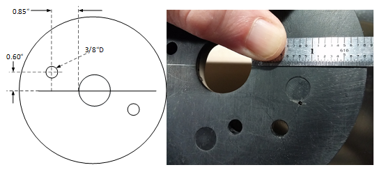
Drill small pilot holes using your pin vise drill (for precision of placement) and then drill out the 3/8”D holes with a wood bit. You’ll discover something about drilling in the plastic the SEOS15 is made from -- that it is made from SERIOUSLY thick plastic, but it cuts easily. The drilling will start slow, but then when the drill gets about halfway through, it will suddenly dig in and pull with some violence through the CD mount! So don’t push too hard. This won’t cause any real problem here, but would become one in the next step when you drill the midrange ports, as the drill will want to gouge into the visible opposite wall of the horn when it jumps through. So these holes are good practice for controlling the drill.
To prepare the midrange mounting area, you need to cut away the support strut that is intended to strengthen the CD mounting plate, on the side that doesn’t have the SEOS logo. The plate is very thick and strong, and the tweeters won’t be all that heavy, so the strut is both un-needed and in the way. I used an old “un-cherished large wire cutters” to trim away the plastic strut a quarter inch or so at a time, you can do that or use a saw or any other means you have available to cut the ridge down approximately flush with the outside of the horn.
Lay the horn on its wide side on a table. Now, take your flexible scale and on the side you removed the strut/ridge from, measure and mark (or scratch) a line 1.25 inches out from the back of the mounting plate (see the sketch below). Measure along the body of the horn, with the scale pushed to the outside surface of the horn. Then locate the center of the horn again (where you removed that ridge from) and measure and mark 0.90 inches on either side of the center, at the previously marked line. At those points, use the pin vice drill to start small holes into the plastic, making the hole perpendicular to the TABLE (not to the horn wall).

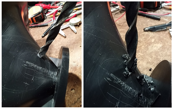
Now, here is where it gets (a little) more complicated. So far, out of the 8 ports I’ve drilled like this into plastic waveguide walls, only two have happened without gouging into the opposite wall when the drill yanks its way through! I don’t have a lot of horns to keep doing this with, but the method that has worked successfully (well, except once!) was to have a piece of wood stuffed into the horn throat from the other side so the drill bashes into it rather than into the plastic wall. A 1” dowel worked once, but another time, the drill still pushed it aside and went past anyway. The best approach seems to be to use a piece of MDF sheet, cut to have a corner that is a little less than 90 degrees and pushed into the throat, to catch the drill. I’ll leave coming up with a way to hold the MDF in there during drilling to you (I held it by hand, but that was a bit clumsy). If the drill does tear through, it isn’t a disaster, only cosmetic – sand down the gouge and smear in a little wood putty and it will be fine. But it’s a shame to deface the pretty surface if you can avoid it.
Drilling also requires care because we want it near the desired angle with the horn walls. To get the port down near the tweeter’s throat, the hole is to be drilled at an angle toward the tweeter (rather than straight down perpendicularly through the horn wall). Set the SEOS on a flat bench, which will result in the CD mounting plate being at an angle to the bench. Start with the 7/16 brad-point drill bit perpendicular to the horn wall, so that it begins boring in at the right location where the pin vice hole was made. Then, when the drill begins to cut its outer diameter into the horn wall, tip the drill upwards with the drill running to be perpendicular to the TABLE (not the horn wall anymore). See photos below. This is easier than it sounds, just align the drill bit (via eyeball) with some vertical edge in the room, when checking it from several directions while you drill. The more difficult part is when the drill starts to come through the wall and gets over-enthusiastic about pulling in!
since there was a question about drilling holes (ports) for the midrange --
(from a writeup I did a while ago but didn't blog yet
Mods to the horn involves first moving the two tweeter mounting holes to get them away from the midrange that would otherwise block them; then cutting port holes for the midrange; then fabricating and attaching a mounting plate for the midrange and filling in some resulting volume. None of it is too hard, and I avoided making changes that couldn’t be specified and duplicated accurately enough on a shop bench. But it will take a little care.
___
First, cut new tweeter mounting holes. Place the SEOS15 mouth down onto a table, and take your metal scale and mark the center line across the horn’s mounting plate (you can see the position by looking at the mold seams on the side). Then, use the scale to mark the positions for the new holes as shown below.
Drill small pilot holes using your pin vise drill (for precision of placement) and then drill out the 3/8”D holes with a wood bit. You’ll discover something about drilling in the plastic the SEOS15 is made from -- that it is made from SERIOUSLY thick plastic, but it cuts easily. The drilling will start slow, but then when the drill gets about halfway through, it will suddenly dig in and pull with some violence through the CD mount! So don’t push too hard. This won’t cause any real problem here, but would become one in the next step when you drill the midrange ports, as the drill will want to gouge into the visible opposite wall of the horn when it jumps through. So these holes are good practice for controlling the drill.
To prepare the midrange mounting area, you need to cut away the support strut that is intended to strengthen the CD mounting plate, on the side that doesn’t have the SEOS logo. The plate is very thick and strong, and the tweeters won’t be all that heavy, so the strut is both un-needed and in the way. I used an old “un-cherished large wire cutters” to trim away the plastic strut a quarter inch or so at a time, you can do that or use a saw or any other means you have available to cut the ridge down approximately flush with the outside of the horn.
Lay the horn on its wide side on a table. Now, take your flexible scale and on the side you removed the strut/ridge from, measure and mark (or scratch) a line 1.25 inches out from the back of the mounting plate (see the sketch below). Measure along the body of the horn, with the scale pushed to the outside surface of the horn. Then locate the center of the horn again (where you removed that ridge from) and measure and mark 0.90 inches on either side of the center, at the previously marked line. At those points, use the pin vice drill to start small holes into the plastic, making the hole perpendicular to the TABLE (not to the horn wall).
Drilling also requires care because we want it near the desired angle with the horn walls. To get the port down near the tweeter’s throat, the hole is to be drilled at an angle toward the tweeter (rather than straight down perpendicularly through the horn wall). Set the SEOS on a flat bench, which will result in the CD mounting plate being at an angle to the bench. Start with the 7/16 brad-point drill bit perpendicular to the horn wall, so that it begins boring in at the right location where the pin vice hole was made. Then, when the drill begins to cut its outer diameter into the horn wall, tip the drill upwards with the drill running to be perpendicular to the TABLE (not the horn wall anymore). See photos below. This is easier than it sounds, just align the drill bit (via eyeball) with some vertical edge in the room, when checking it from several directions while you drill. The more difficult part is when the drill starts to come through the wall and gets over-enthusiastic about pulling in!
Last edited:
The midrange mounting plate
(from a writeup I did a while ago but didn't blog yet: )
The outside of the horn isn’t a nice flat plane (I have to remember to give Erich some grief about that), so a mounting board has to be added there and attached with an air-tight seal. I did this using thin 1/8” (3mm) “CraftPly” from the local TruValue hardware store; if you have a piece of undrilled FR-4 circuit board that would do as well or better. Basically you need something flat, thin and strong enough to hold some wood or sheet metal screws for mounting the midrange driver.
Start with 4.35”x4.35” square boards and find and mark the center point of each by drawing lines between the corners. Use your compass to draw concentric circles on the boards around that point, one with radius of 1.75 inches and one with radius of 2.00 inches (see sketch below). The inner circle is the clearance for the driver, the outer circle marks the outside of the where the mounting gasket will lie. Cut out the middle circle with the jigsaw, and drill small holes (about 1/8”diameter) into various areas around the panels EXCEPT between the circles where the gasket must seal and NOT at the places where the driver mounting screws will need to attach. These small holes are to improve the grip of the epoxy putty that will be used to attach the panel to the horn. The panel is just a piece of board with some holes cut into it.
Finally, use the driver to trace an outline on the panel and cut away some of the excess at the lower left corner. That’s to provide a little better access to a tweeter mounting bolt after this panel is mounted to the horn.

Set the panel on the horn, with its lower edge up against the back of the tweeter mounting plate. Look to see how much space there is between the panel and the plat in the area around the large hole. Scuff up the surface of the horn to improve grip of the putty (you can even drill some shallow holes in the area if you want). Take a 2oz epoxy putty stick (from most hardware stores or Harbor Freight) for attaching the plate and sealing the gap of each waveguide. Wear rubber gloves when handling the putty, both to keep your hands from smelling like epoxy and to keep skin oils out of the putty. Follow instructions for the putty (make sure you knead the stuff fully but attach within a few minutes), and press a rope shape of the kneaded putty around under the hole, with more putty where will be needed. Then press it onto the horn, making sure the board is centered and that the port holes in the horn walls are not obstructed. Give the epoxy overnight to harden.
Here’s a photo of what you’re going for:

A small air volume between the midrange driver and the ports provides acoustic lowpass filtering to the response, but the volume made needs to be reduced to obtain enough HF. If you want to go all out, probably the best way to do that would be to fill the volume to the surface (except between the ports and the middle of the cone) with more epoxy putty, but that can get expensive. When I was testing, I just used inexpensive plumbers’ putty (from about any hardware store) and after getting it where it needed to be, left it in. It’s been ok for over a month now, so I think it will be ok for permanent use. Make sure the fill does not protrude higher than the panel surface (drag a straight-edge across the surface to make sure), and keep the air path from near the cone center to the ports open. Here is a photo of how one of mine look:

(from a writeup I did a while ago but didn't blog yet: )
The outside of the horn isn’t a nice flat plane (I have to remember to give Erich some grief about that), so a mounting board has to be added there and attached with an air-tight seal. I did this using thin 1/8” (3mm) “CraftPly” from the local TruValue hardware store; if you have a piece of undrilled FR-4 circuit board that would do as well or better. Basically you need something flat, thin and strong enough to hold some wood or sheet metal screws for mounting the midrange driver.
Start with 4.35”x4.35” square boards and find and mark the center point of each by drawing lines between the corners. Use your compass to draw concentric circles on the boards around that point, one with radius of 1.75 inches and one with radius of 2.00 inches (see sketch below). The inner circle is the clearance for the driver, the outer circle marks the outside of the where the mounting gasket will lie. Cut out the middle circle with the jigsaw, and drill small holes (about 1/8”diameter) into various areas around the panels EXCEPT between the circles where the gasket must seal and NOT at the places where the driver mounting screws will need to attach. These small holes are to improve the grip of the epoxy putty that will be used to attach the panel to the horn. The panel is just a piece of board with some holes cut into it.
Finally, use the driver to trace an outline on the panel and cut away some of the excess at the lower left corner. That’s to provide a little better access to a tweeter mounting bolt after this panel is mounted to the horn.
Set the panel on the horn, with its lower edge up against the back of the tweeter mounting plate. Look to see how much space there is between the panel and the plat in the area around the large hole. Scuff up the surface of the horn to improve grip of the putty (you can even drill some shallow holes in the area if you want). Take a 2oz epoxy putty stick (from most hardware stores or Harbor Freight) for attaching the plate and sealing the gap of each waveguide. Wear rubber gloves when handling the putty, both to keep your hands from smelling like epoxy and to keep skin oils out of the putty. Follow instructions for the putty (make sure you knead the stuff fully but attach within a few minutes), and press a rope shape of the kneaded putty around under the hole, with more putty where will be needed. Then press it onto the horn, making sure the board is centered and that the port holes in the horn walls are not obstructed. Give the epoxy overnight to harden.
Here’s a photo of what you’re going for:
A small air volume between the midrange driver and the ports provides acoustic lowpass filtering to the response, but the volume made needs to be reduced to obtain enough HF. If you want to go all out, probably the best way to do that would be to fill the volume to the surface (except between the ports and the middle of the cone) with more epoxy putty, but that can get expensive. When I was testing, I just used inexpensive plumbers’ putty (from about any hardware store) and after getting it where it needed to be, left it in. It’s been ok for over a month now, so I think it will be ok for permanent use. Make sure the fill does not protrude higher than the panel surface (drag a straight-edge across the surface to make sure), and keep the air path from near the cone center to the ports open. Here is a photo of how one of mine look:
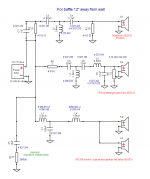
Someone pointed out to me that I never posted the final passive crossover schematic for the SmallSyns, so here it is for anyone who might be considering making these or something like them.
I've got the material for the next build now (the shelf-ported version), but not a chance to go cut it yet or start building. I'm going to put that together before doing the full build blog, since there will probably be some adjustments to the port and maybe the drawings to get it right. Might be schematic changes, too (but I hope not!). I'll document the progress here, as usual, though. Mistakes that get made on the way, too, as usual!
I've got the material for the next build now (the shelf-ported version), but not a chance to go cut it yet or start building. I'm going to put that together before doing the full build blog, since there will probably be some adjustments to the port and maybe the drawings to get it right. Might be schematic changes, too (but I hope not!). I'll document the progress here, as usual, though. Mistakes that get made on the way, too, as usual!
Attachments
Hi Bill:
Good luck with your build. I've been meaning to pass on a tip about epoxy vs plumber's putty. I think bondo is pretty good for this; more permanent than plumber's putty, not too expensive, sands easily. I was told to go real easy on the hardener and you'll get lots of setup time. I used too much hardener and I lost the race to get it placed before it hardened, so I'm pretty sure that is good advice.
Good luck with your build. I've been meaning to pass on a tip about epoxy vs plumber's putty. I think bondo is pretty good for this; more permanent than plumber's putty, not too expensive, sands easily. I was told to go real easy on the hardener and you'll get lots of setup time. I used too much hardener and I lost the race to get it placed before it hardened, so I'm pretty sure that is good advice.
- Home
- Loudspeakers
- Multi-Way
- Small Syns