
K3149 specs
Uuuhhmm , sorry for my short memory.
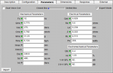
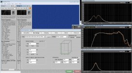
I promised the measured specs of the K3149, looked them up and attached the parameter window from BB Pro.
I DID found out that (as I can recall);
- Both my (reconed) drivers measured differently and after several attempts kept measuring differently (consistently wrong is also consistent....)
- The drivers were NOT burned in
- They kind of matched with a K3148 which seems to be a close related driver
- I did an "average" calculation of each parameter, with the specs in the attachment as a result. That would (likely????) flatten out the measuring errors.
When I used these parameters in BB Pro I got a similar design as the standard SRM12X, so must be kind of OK.
What I do NOT understand is the somewhat smaller BR-vent, at least as far I can see on images. I did some measurements of the vents on images and recalculated them with the ratio I got by measuring the total width of the enclosure on the same image and using the specified width. Specified / measured on image = ratio.
They seem SMALLER than BB Pro suggests, but I get similar SPL graphs with BB Pro as others have found AND Tannoy published. They could be made longer by Tannoy to get the same vent volume, but that would increase vent speed (smaller diameter is higher air speed in vent). Looking close at some pictures the vent seems to be the thickness of the front panel (25 mm). I never got that width the supposed vent diameter of the images and BB Pro.
ANYWAY, on the design I posted earlier, I used my BB Pro vent size.
Have NOT been building yet.
I do intend to replace the original filter with new improved components. The filter on the high unit for level correction will most likely be replaced by an LPAD with fixed reistors and a multistep switch.
kind regards,
Frans
Uuuhhmm , sorry for my short memory.
I promised the measured specs of the K3149, looked them up and attached the parameter window from BB Pro.
I DID found out that (as I can recall);
- Both my (reconed) drivers measured differently and after several attempts kept measuring differently (consistently wrong is also consistent....
)- The drivers were NOT burned in
- They kind of matched with a K3148 which seems to be a close related driver
- I did an "average" calculation of each parameter, with the specs in the attachment as a result. That would (likely????) flatten out the measuring errors.
When I used these parameters in BB Pro I got a similar design as the standard SRM12X, so must be kind of OK.
What I do NOT understand is the somewhat smaller BR-vent, at least as far I can see on images. I did some measurements of the vents on images and recalculated them with the ratio I got by measuring the total width of the enclosure on the same image and using the specified width. Specified / measured on image = ratio.
They seem SMALLER than BB Pro suggests, but I get similar SPL graphs with BB Pro as others have found AND Tannoy published. They could be made longer by Tannoy to get the same vent volume, but that would increase vent speed (smaller diameter is higher air speed in vent). Looking close at some pictures the vent seems to be the thickness of the front panel (25 mm). I never got that width the supposed vent diameter of the images and BB Pro.
ANYWAY, on the design I posted earlier, I used my BB Pro vent size.
Have NOT been building yet.
I do intend to replace the original filter with new improved components. The filter on the high unit for level correction will most likely be replaced by an LPAD with fixed reistors and a multistep switch.
kind regards,
Frans
Attachments
K3149 in a Transmission Line
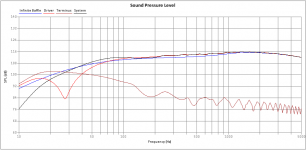
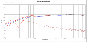
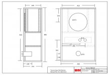
I did a quick TL 3 segment version with this driver. Looks better in the Low area as opposed to a Bass Reflex version. The BR starts struggling around the Fs area of the driver and falls of pretty steep. The TL roll off starts slightly earlier but much more gentle.
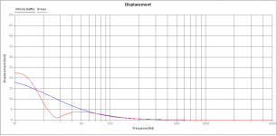
I've added an SPL and excursion graph in a TL of 93 x 54 x 34 cm (outside dims) @ 100 watts.
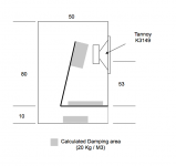
Driver offset is at 53 cm (that is from the start of the TL). Added a sketch, cabinet is 30 cm internal width. Only requires 3 patches of damping at designated area according to the simulation to et nice flat response.
Looks very nice and HiFi.
Taming the mids and w're good to go??
kind regards,
Frans
I did a quick TL 3 segment version with this driver. Looks better in the Low area as opposed to a Bass Reflex version. The BR starts struggling around the Fs area of the driver and falls of pretty steep. The TL roll off starts slightly earlier but much more gentle.
I've added an SPL and excursion graph in a TL of 93 x 54 x 34 cm (outside dims) @ 100 watts.
Driver offset is at 53 cm (that is from the start of the TL). Added a sketch, cabinet is 30 cm internal width. Only requires 3 patches of damping at designated area according to the simulation to et nice flat response.
Looks very nice and HiFi.
Taming the mids and w're good to go??
kind regards,
Frans
Attachments
Last edited:
Soffit / Flush mounting
Came to my mind, these SRM12X were meant to be studio speakers right?
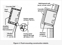
Soffit or Flush mounting has been applied to monitors in a studio, mostly to avoid cancelation as a result of back wave radiation (or whatever it is called). I mean, low frequences crawl around a cabinet and if that cabinet sits in front of a wall (usually the case in a studio / any room your in) those waves will hit the wall and bounce back into the room, delayed in time and interfere with the direct radiated forward wave, hence cancelation and other messing around. We don't want that, so mount the cabinet "flush" with the wall.
I solves these cancelation issues, AND as a bonus, adds some 4 - 6 dB in the low regions (200 Hz downwards as stated by Genelec).
Now THAT is nice, if you need more low, here you have it, all for free. Well, you need to bang 2 holes in your room, but HEY, w're audio freaks so who cares....
Uuuhhh Girl friend??? Nehh, when done quick and filled with your neat new self build musical wonder cabinets sounding all nice and stuff, she'll get over it.... They always do in the end......
Oooh well, that's my 5 cents..
So a Transmission Line of 95 x 54 x 33 cm outside (rough measures) and flush mounted, mat rock the boat.
I added about 4 dB to the SPL graph to show what it COULD be like.
Graph 1 is added dB, picture 2 is "how to soffit" by Genelec (and others).
kind regards,
Frans
Came to my mind, these SRM12X were meant to be studio speakers right?
Soffit or Flush mounting has been applied to monitors in a studio, mostly to avoid cancelation as a result of back wave radiation (or whatever it is called). I mean, low frequences crawl around a cabinet and if that cabinet sits in front of a wall (usually the case in a studio / any room your in
) those waves will hit the wall and bounce back into the room, delayed in time and interfere with the direct radiated forward wave, hence cancelation and other messing around. We don't want that, so mount the cabinet "flush" with the wall.I solves these cancelation issues, AND as a bonus, adds some 4 - 6 dB in the low regions (200 Hz downwards as stated by Genelec).
Now THAT is nice, if you need more low, here you have it, all for free. Well, you need to bang 2 holes in your room, but HEY, w're audio freaks so who cares....
Uuuhhh Girl friend??? Nehh, when done quick and filled with your neat new self build musical wonder cabinets sounding all nice and stuff, she'll get over it....
They always do in the end......Oooh well, that's my 5 cents..
So a Transmission Line of 95 x 54 x 33 cm outside (rough measures) and flush mounted, mat rock the boat.
I added about 4 dB to the SPL graph to show what it COULD be like.
Graph 1 is added dB, picture 2 is "how to soffit" by Genelec (and others).
kind regards,
Frans
Attachments
Soffit / Flush mounting
Additional to my previous post, I found a even better version. Since there could be a build up of low frequency material when soffit mounting, the addition of a bass trap BELOW the speaker gives the opportunity to tune the low end.
I've added a picture of the combination of soffit mounting and a bass trap. When you can build speakers, you should be able to build this as well.
I got this picture from SAE, thanks
kind regards,
Frans
Attachments
Made up my mind
Finaly made up my mind (thanks to Charles) and this one will split up in 2 projects (or actually 3);
1 - I did make a solid recreation drawing of the original SRM 12X cabinet (that's one project), even though I know it's not a killer bass. It's how it was in that period, I do see some famous sound engineers use them as near fields.
2 - I did make some nice progress on putting this driver into a 3 fold stepped TL (next project)
3 - I will start a new Thread for a 12" "Poor man's Tannoy DMT" (last project).
Why?, because we can...
No seriously, I will start the build of my home recording studio, a Hybrid setup with Presonus Studio one on a Mac Pro, with a 56 channel analog mixer to make it Hybrid. I got all the stuff (second hand mostly) and did some tests, VERY nice to work with. Mainly will be doing mixing, NOT recording, also as a live demo of my WAE studio speaker-line.
For that studio, I want to use the K3149 in its original format, that's why project one. Next to that, I would love to hear these K3149's in a TL (second project).
Finally, for my WAE small business, I want to setup an "affordable studio monitor line". As main monitors, I want to be able to deliver a big monitor, as good as possible sounding, but VERY affordable. The real deal is already on the market, from various brands, but VERY expensive. Wonder if it is possible to build a "poor man's Tannoy DMT" based on commercially available low cost components (Coaxcials). That will be project 3.
I like the idea from Charles, adding a 12" to the K3149 like the Tannoy FSM, but that would be a "one off". Project 3 will be a new thread "The poor man's Tannoy DMT".
For Project 3:
The absolute cheapest way to a 12" coaxial is the Eminence Beta 12CX for £72 with a P-Audio 1" screw in compression driver which cost around £30.
The next cheapest will cost about twice that.
Btw way back when I think I forgot to mention that the K3149 is the same as the K3148. Tannoy called it '49 when they sold it as a finished speaker and '48 when sold as a kit.
If I'd start again today instead of the Volt I would get one or even two BMS 12S330 per side.
One of the reasons being that the Volt costs £500 inc VAT these days and the BMS £152! When I built mine the Volt was around 300 and the BMS didn't exist.
In fact after a short discussion with myself I'd use two BMS per side in ported cabs since they can live in relatively small cabs of 60L each.
Or two sharing one T/L...hhmmmmm....
Note that the quoted 96dB/1W are ridiculously optimistic, they do around 90 in real life where it matters.
Mind reading....
Hey Charles, that's exactly what I had in mind, even worse, designed a first version with 1 Beta 12CX and 1 Beta 12A-2. I did use a Celestion CDX1-1446 as driver though @ 53 euro.
Both 12" perform the same. The Beta 12CX Coax will be crossed around 2.2kHz. The Beta 12A-2 will have a low-pass of 220Hz or so to ensure consistent point source with the Coax 12". So in fact its a special kind of 3-way where the traditional mid now is the Coax 12" at same high-pass (40 Hz) as the bass driver.
Keep you posted.
For Project 3:
The absolute cheapest way to a 12" coaxial is the Eminence Beta 12CX for £72 with a P-Audio 1" screw in compression driver which cost around £30.
Hey Charles, that's exactly what I had in mind, even worse, designed a first version with 1 Beta 12CX and 1 Beta 12A-2. I did use a Celestion CDX1-1446 as driver though @ 53 euro.
Both 12" perform the same. The Beta 12CX Coax will be crossed around 2.2kHz. The Beta 12A-2 will have a low-pass of 220Hz or so to ensure consistent point source with the Coax 12". So in fact its a special kind of 3-way where the traditional mid now is the Coax 12" at same high-pass (40 Hz) as the bass driver.
Keep you posted.
Attachments
Here is the PM-DMT, Poor Man's Tannoy DMT project;
http://www.diyaudio.com/forums/multi-way/326075-poor-mans-tannoy-dmt-aka-pm-dmt.html#post5514587
http://www.diyaudio.com/forums/multi-way/326075-poor-mans-tannoy-dmt-aka-pm-dmt.html#post5514587
Hey Charles, that's exactly what I had in mind, even worse, designed a first version with 1 Beta 12CX and 1 Beta 12A-2. I did use a Celestion CDX1-1446 as driver though @ 53 euro.
Both 12" perform the same. The Beta 12CX Coax will be crossed around 2.2kHz. The Beta 12A-2 will have a low-pass of 220Hz or so to ensure consistent point source with the Coax 12". So in fact its a special kind of 3-way where the traditional mid now is the Coax 12" at same high-pass (40 Hz) as the bass driver.
Keep you posted.
2.2k is a bit high for a 12" which is one of the reasons I mentioned P Audio drivers as they have two or three 1'screw-in drivers with a recommended xover frequency of 1.2 or 1.5k which is much nearer to where you want to be. Price being the other one obviously.
Eminence also do 8 and 10 inch CXs so you could produce a whole family!
Tannoys 215DMT has two operating modes: Either 2way where the bass driver and the cone section of the DualConcentric run parallel or 3way where the bass driver covers everything to 250Hz (I think) and the DC takes over from there.
I prefer the latter.
(Not sure if I should have posted in your new thread instead but I am answering your post directly so here it is)
Continue as project, the REAL SRM12X
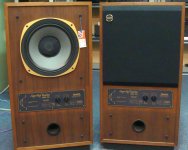
This thread started with me being all hyped up about finally having a pair of Tannoy DC's from the early 80's.
Then all hell broke loose, because we always want to make the original better, for good reasons mostly.
So I decided to split up the thread,
- use the old K3149 (reconed) for the original SRM12X (this thread)
- and go for a 3-way DC aiming at studio usage. It's called to PM-DMT because the new thread started with de Tannoy DMT as an example.
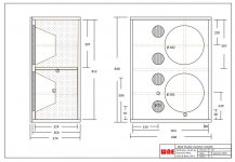
Anyway, THIS thread is all about building the SRM12X, as in the attached picture.
I do need to double check on the dimensions, but guess this will be the own.
Will build it using good quality MDF and apply a veneer job. The grey area's is bracing, hey some detail changes is OK isn't it. Also need to work on the cross-over, only have one
to be continued,
kind regards.
This thread started with me being all hyped up about finally having a pair of Tannoy DC's from the early 80's.
Then all hell broke loose, because we always want to make the original better, for good reasons mostly.
So I decided to split up the thread,
- use the old K3149 (reconed) for the original SRM12X (this thread)
- and go for a 3-way DC aiming at studio usage. It's called to PM-DMT because the new thread started with de Tannoy DMT as an example.
Anyway, THIS thread is all about building the SRM12X, as in the attached picture.
I do need to double check on the dimensions, but guess this will be the own.
Will build it using good quality MDF and apply a veneer job. The grey area's is bracing, hey some detail changes is OK isn't it. Also need to work on the cross-over, only have one
to be continued,
kind regards.
Attachments
Last edited:
You will struggle replicating your single crossover!
If you look at it closely you'll find that it is based around an autoformer which is impossible to get hold of.
It is possible to have them remade but that is not cheap and you need one to be measured/copied which you have.
The other way would be to use the crossover from the DC4000 (same driver) but no autoformer. I think the schematic for this exists in the archives of the Tannoy Yahoo group. You'll have to join for access I think. You would lose the roll off adjustment ability from the autoformer based crossover though.
You will struggle replicating your single crossover!
If you look at it closely you'll find that it is based around an autoformer which is impossible to get hold of.
It is possible to have them remade but that is not cheap and you need one to be measured/copied which you have.
The other way would be to use the crossover from the DC4000 (same driver) but no autoformer. I think the schematic for this exists in the archives of the Tannoy Yahoo group. You'll have to join for access I think. You would lose the roll off adjustment ability from the autoformer based crossover though.
Yes, the cross-over will be an issue. However, I'm not that pessimistic. If you look at the schema, it's the "T1" (as called by you the autoformer) that needs to be fixed (as per the options you mentioned);
- Find one that's the original (little to NO chance at all)
- Have one made (using the original is do-able)
Third option;
- Make up my own alternative.
Well, the latter maybe is not such a big issue as it may look like (unless I am very wrong here...). I've had an education in electronics and this seems to me just another mulitab coil. It is a coil and resister combination (T1 and R2) because R2 is in parallel from the shared "BK" point and the central point of the switch S1.
The connection of the HF between the "BK" connection and the "red" wire is "full throttle" (or called +3dB) an coil only (R2 open ended). All the others "BK" and orange, "BK" and yellow, etc. change the number of windings, hence change the coil value, hence change output. Via the "S1" central point, which goes to the next "S2a & S2b" switch the second filter setting is designed. That is the roll-off network selection, which can be build as is. It selects the roll-off frequency.
As my own alternative, I could be using a number of coils (Value "BK - Red, etc.) , which reduce in windings in the same rate (because the level reduces in 1,5 dB per step). So 5 coils in total connected to "BK" and each point of the S1 switch...
I'm not a cross-over specialist (so this is my current view on the network), but I know a friend who is. So I'll have to consult him for a replacing schema.
Cross-over will be new build with "better" components. ALLTHOUGH, I did read an article stating that this will not always be an improvement. The "old" components combined with the driver produce the current "character". Changing the components may result in changing the character for the worse, which remains to be seen.
Also, in parallel, I am on the look-out for a second original filter (also little chance) via the Yahoo group, but not much success yet.
kind regards.
Attachments
I've had an education in electronics and this seems to me just another mulitab coil.
Bingo!
: http://www.communitypro.com/sites/default/files/Autoformer Tech Note_v2.pdfGM
Autoformer....
Found on the WWW;
Actually they are correctly called AVC for Autoformer Volume Control. They have a single continous winding with the taps logarithmically spaced for X dB steps.
So that's what we will look for, there seems to be companies that deliver them....
Other alternative, use R's (resisters) only as a attenuation network before the HF S2 network. Maybe they used the AVC to avoid expensive (if available by then "high power" R's ?? Just guessing here.
kind regards.
Last edited:
Your the man !!!.
Thanks.
Finding a single crossover without a driver is highly unlikely but if you can replicate the autoformer you could make a lot of friends in the Yahoo group and elsewhere where Tannerds congregate!
Chances are growing there are places that build this stuff, maybe via GM's posted link. Diving into it.
kind regards.
- Home
- Loudspeakers
- Multi-Way
- Tannoy Super Red Monitor Project