In general when combining 2 drivers, you want to make sure that the off-axis response of the larger driver hasn't dropped off too much by the time you get to the xo point. In point of fact, the measurements that SB supplies with that Satori driver show exception off-axis response for a driver of that size. So exceptional in fact that I'm somewhat skeptical of the results without 3rd party confirmation. So I'm not going to recommend it with that ribbon but if you really want to try it, then have at her.
Let's go back to the beginning though and make sure that you are starting with good files. Why don't you post the FR and impedance graphs of all the drivers you are interested in so I can see if they are correct. To do this I'm going to suggest that you use XSim as the program to graph them all as this will give you an easy introduction on how to use it. You don't have to create any wiring or xo's, just open up the appropriate number of drivers (drag and drop really) and right clicking and using Tune for each one, import the correct files. Label them so I know which is which.
If you don't know how to attach Xsim, here's what bwaslo, the designer, suggests:
"A way to do it is to zip up the file (unless you selected otherwise, it is probably in your C:\Users\Public\XSim\designs folder).
**To zip up a file:**
Find the .dxo file in your Windows File Explorer
Right-click on the file name, left-click on the menu "Add to...".
Change "Save as type" to "Zip archive (*.zip)".
In the left pane, select the folder you want the zip file to be saved in, Somewhere easy to find, such as your Documents folder.
Give it a recognizeable name, then click "Save"
Then attach the new zip file to your post.
Anyone wanting to open your file then in Xsim will need to go to where their copy of the zip file got downloaded to, and uzip it somewhere convenient. Double-click on the file name to open it up (or do "File Load" from inside Xsim)."
In general when combining 2 drivers, you want to make sure that the off-axis response of the larger driver hasn't dropped off too much by the time you get to the xo point. In point of fact, the measurements that SB supplies with that Satori driver show exception off-axis response for a driver of that size. So exceptional in fact that I'm somewhat skeptical of the results without 3rd party confirmation. So I'm not going to recommend it with that ribbon but if you really want to try it, then have at her.
Let's go back to the beginning though and make sure that you are starting with good files. Why don't you post the FR and impedance graphs of all the drivers you are interested in so I can see if they are correct. To do this I'm going to suggest that you use XSim as the program to graph them all as this will give you an easy introduction on how to use it. You don't have to create any wiring or xo's, just open up the appropriate number of drivers (drag and drop really) and right clicking and using Tune for each one, import the correct files. Label them so I know which is which.
If you don't know how to attach Xsim, here's what bwaslo, the designer, suggests:
"A way to do it is to zip up the file (unless you selected otherwise, it is probably in your C:\Users\Public\XSim\designs folder).
**To zip up a file:**
Find the .dxo file in your Windows File Explorer
Right-click on the file name, left-click on the menu "Add to...".
Change "Save as type" to "Zip archive (*.zip)".
In the left pane, select the folder you want the zip file to be saved in, Somewhere easy to find, such as your Documents folder.
Give it a recognizeable name, then click "Save"
Then attach the new zip file to your post.
Anyone wanting to open your file then in Xsim will need to go to where their copy of the zip file got downloaded to, and uzip it somewhere convenient. Double-click on the file name to open it up (or do "File Load" from inside Xsim)."
Fab, this is actually starting to make sense now. A quick project review today and this is where i'm at. Please stop me if its a mistake. I'm going to keep things simple and go with a dome tweeter and no waveguide. I think this will really simplify the design and as a result reduce my headaches
") There's always the next project. Where I can go with ribbon tweeters and slightly more exotic designs
There's always the next project. Where I can go with ribbon tweeters and slightly more exotic designs So driver wise, i'm going with one of your earlier recommendations.
T: SB29RDNC-C000-4
M: SATORI MW13P-8
W: Peerless HDS-P835025
I had a look around at waveguide adapters for SB29RDNC, however it looks like this tweeter has a sealed faceplate.
I've already modeled the Woofer and Mid, so will do the same for the Tweeter unless you see something wrong with this approach. Will post the file for the drivers tomorrow evening and tonight i'll have another look at XSim now you've given me some good pointers on how to use it
I've added the data to Xsim as requested. One thing I wasn't sure of was.. Response molder for the tweeter. There are no VAS measurements, therefore I wasn't able to model in the same way as I did with the other drivers.. i'm not sure if i got the tweeter right or not.
Here's a link to download the XSim file and also the FRD's and ZMA's, which with the exception of the Tweeter, have been simmer and phased with a degree of confidence
https://drive.google.com/file/d/0Bwwef9FGi6Gienk3YllJalAzdzA/view?usp=sharing
Here's a link to download the XSim file and also the FRD's and ZMA's, which with the exception of the Tweeter, have been simmer and phased with a degree of confidence
https://drive.google.com/file/d/0Bwwef9FGi6Gienk3YllJalAzdzA/view?usp=sharing
Ok, it seems to me that you are set on the Satori mid, so a dome tweeter would be a better match.
You only have to do box modeling if the driver is open back. Tweeters generally are closed so therefore the response doesn't change when you put it into a cabinet except for diffraction effects. So you don't have to splice on the LF response as you do with the mid and the woofer.
Sorry, you are going to have to tell me how to open your files because I don't know how to do it in the link you attached.
When you click on the link you should see the google drive download page for the file. On the page there should be a download icon. Normally a down arrow. That's how you download the zip file. If that doesn't work, do you have a preferred method?
Mid wise, the Satori seems to be a good choice to go with a done. There seems to be so many options / combos I'm happy to settle on that one
Mid wise, the Satori seems to be a good choice to go with a done. There seems to be so many options / combos I'm happy to settle on that one
On the page there should be a download icon. Normally a down arrow.
Nope, not getting any download action from that page.
It does work jReave it's just not very intuitive.
On the page that pops up move the mouse cursor to the top of the web-page. A tool-bar should appear if it isn't already visible. On the bar there are several icons, one of which is an arrow pointing down with a horizontal bar at the apex of the arrows point. This is what you need to click to download the files.
Note that I am signed into google on my machine although I don't think that should matter.
The tweeter response looks okay but the midrange and woofer do not. The problem is with the low frequency part of the graphs.
I have no familiarity with the measurement-less approaches to speaker design as I've always measured for myself, but I am guessing that somewhere during the process you are supposed to simulate your drivers bass alignment in the box that you are intending to use. Then you splice it to the traced (high frequency) frequency response at a suitable frequency. Ie your simulated bass alignment takes the place of a near field measurement. After you've spliced the simulated bass alignment to the traced frequency response you'd need to apply baffle diffraction and baffle step effects to it.
I have no familiarity with the measurement-less approaches to speaker design as I've always measured for myself, but I am guessing that somewhere during the process you are supposed to simulate your drivers bass alignment in the box that you are intending to use. Then you splice it to the traced (high frequency) frequency response at a suitable frequency. Ie your simulated bass alignment takes the place of a near field measurement. After you've spliced the simulated bass alignment to the traced frequency response you'd need to apply baffle diffraction and baffle step effects to it.
Thanks Guys. With regards to the low frequency parts of the of the graph. I used Response Modeler and the following guide to help me get through it. I didn't action the "Splice Box Plot to Response Model" item because I seems to throw the graphs off and it didn't seem to apply to this design. Maybe that's the issue?
https://sites.google.com/site/undefinition/simulated-measurements
Looking forward to more feedback
https://sites.google.com/site/undefinition/simulated-measurements
Looking forward to more feedback
Step 6 in your link above - splicing the box response onto the measured FR should indeed be included with the woofer and the mid.
Ok great, I'll go through the guide again and provide an updated zip file. Bear with me guys
Here are the updated set of files.
https://drive.google.com/file/d/0Bwwef9FGi6GiV3FHdEh1TlhJQms/view?usp=sharing
I've re-checked the box modeling in BoxyCAD and WinISD, re-checked all the data and reran Response Modeler, now with box plot splicing
One thing that's bothering me is the large drop at 1.5K on the MW13P-8. I think this is a limitation of the driver? Is that an issue. Should we be looking to swap that driver for something else as good as the MW13P-8 but with out the 1.5k drop?
Those look much better although I would probably splice at around 300-400Hz to create a smoother response, most notably that blip at around 200Hz in the MW13s response.
From a quick sim a 300Hz 4th order LW looks like it should work very well between the bass and midrange. I went for a 2500Hz 4th order LW. That'd also work but will need asymmetric slopes for correct phase alignment.
From a quick sim a 300Hz 4th order LW looks like it should work very well between the bass and midrange. I went for a 2500Hz 4th order LW. That'd also work but will need asymmetric slopes for correct phase alignment.
Those look much better although I would probably splice at around 300-400Hz to create a smoother response, most notably that blip at around 200Hz in the MW13s response.
From a quick sim a 300Hz 4th order LW looks like it should work very well between the bass and midrange. I went for a 2500Hz 4th order LW. That'd also work but will need asymmetric slopes for correct phase alignment.
Thanks 5th
What's the purpose of the splice/its relevance to how the FR will look? The splice seem to be an artificial element in the process?Well in your case the entire process is artificial from start to finish and you are using the manufacturers measured data for your process. This is fine for the upper response but not for the roll off in the low end. This roll off is determined entirely by the cabinet that you place the driver in and is important for proper design, especially in a three way where the roll off of the midrange is going to influence the high pass you place on it.
Unless I misinterpreted your question.
Unless I misinterpreted your question.
Well in your case the entire process is artificial from start to finish and you are using the manufacturers measured data for your process. This is fine for the upper response but not for the roll off in the low end. This roll off is determined entirely by the cabinet that you place the driver in and is important for proper design, especially in a three way where the roll off of the midrange is going to influence the high pass you place on it.
Unless I misinterpreted your question.
No, that's what I was referring too. Very interesting that the cab effects the low end so much. When I did the box sim the roll off for the Peerless was between 50-100hz. Are we talking about the same roll off?
Ok, that's looking better but there are still some minor problems.
First about the Satori. Both the 5" and 6.5" drivers have a small dip in their midrange response. I have not heard a single person who has listened to them make a complaint about it. But the decision rests with you.
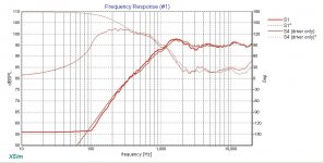
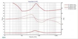
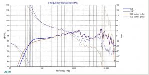
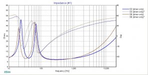
Attached below are comparisons between my files and yours (my results are all in brown - oops except for tweeter Z, both are red):
1 & 2) Tweeter FR and Z
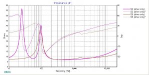
3 & 4) Mid FR and Z
5 & 6) Woofer FR and Z
Tweeter FR: Almost exactly the same except mine is a little smoother and on the low end, my response has been extended. I put the tweeter 33" high and 4.5" from the left side. To 'tail' your response, in Response modeler go to the Adjustable Frequency Response Extension section. Choose around a 800-1000Hz high pass and about a 12dB/octave slope. Save the response and return the last cell to 0dB/octave. Now import that FR back in, splice and add in your diffraction response.
Tweeter Z: It looks like you set your tracing limits incorrectly and that you stopped at 100Hz. Trace the whole thing and just double check your limits.
Mid FR: If you want to use a vented enclosure for the mid, go ahead, but I would go sealed. I modeled it in 4L. Looks like I chose to splice it at just a little lower spl as well. Other than that, they match perfectly.
Mid Z: The low end will obviously be different since we modeled in different types of boxes. However, the upper portion should be the same and is not. And this is not explained I don't think in the tutorials. Here's what you need to do (and you should do the same thing for the woofer as well):
- trace the manufacturer's Z response (this time about 100Hz and up is fine)
- in Response Modeler, model the in-box z as before
- now import the zma file you just traced with the "Import ZMA File To Modify" button and turn the "Overlay Imported zma" button to 'ON'
- from about 100Hz and up, you will now try to align the modeled Z with your imported Z by playing with the Le Expon. and Le Coeff arrows. If that doesn't do the job then you'll need to also use the equalization modules above those. All the variables are user changeable. Let me know if you don't know what Q means in this context or just play with them and you may be able to figure it out.
Woofer FR: Looks like our box modeling was different. I used 20L Fb=33Hz. Again, I think I chose to splice a tiny bit lower in spl. The rest of the FR looks right but I would expect phase to therefore match in that range as well but it does not. Let's see what happens on the next go around.
Woofer Z: Box modeling and Z modifying differences. See above.
Let's see where that gets you on the next try.
First about the Satori. Both the 5" and 6.5" drivers have a small dip in their midrange response. I have not heard a single person who has listened to them make a complaint about it. But the decision rests with you.
Attached below are comparisons between my files and yours (my results are all in brown - oops except for tweeter Z, both are red):
1 & 2) Tweeter FR and Z
3 & 4) Mid FR and Z
5 & 6) Woofer FR and Z
Tweeter FR: Almost exactly the same except mine is a little smoother and on the low end, my response has been extended. I put the tweeter 33" high and 4.5" from the left side. To 'tail' your response, in Response modeler go to the Adjustable Frequency Response Extension section. Choose around a 800-1000Hz high pass and about a 12dB/octave slope. Save the response and return the last cell to 0dB/octave. Now import that FR back in, splice and add in your diffraction response.
Tweeter Z: It looks like you set your tracing limits incorrectly and that you stopped at 100Hz. Trace the whole thing and just double check your limits.
Mid FR: If you want to use a vented enclosure for the mid, go ahead, but I would go sealed. I modeled it in 4L. Looks like I chose to splice it at just a little lower spl as well. Other than that, they match perfectly.
Mid Z: The low end will obviously be different since we modeled in different types of boxes. However, the upper portion should be the same and is not. And this is not explained I don't think in the tutorials. Here's what you need to do (and you should do the same thing for the woofer as well):
- trace the manufacturer's Z response (this time about 100Hz and up is fine)
- in Response Modeler, model the in-box z as before
- now import the zma file you just traced with the "Import ZMA File To Modify" button and turn the "Overlay Imported zma" button to 'ON'
- from about 100Hz and up, you will now try to align the modeled Z with your imported Z by playing with the Le Expon. and Le Coeff arrows. If that doesn't do the job then you'll need to also use the equalization modules above those. All the variables are user changeable. Let me know if you don't know what Q means in this context or just play with them and you may be able to figure it out.
Woofer FR: Looks like our box modeling was different. I used 20L Fb=33Hz. Again, I think I chose to splice a tiny bit lower in spl. The rest of the FR looks right but I would expect phase to therefore match in that range as well but it does not. Let's see what happens on the next go around.
Woofer Z: Box modeling and Z modifying differences. See above.
Let's see where that gets you on the next try.
Attachments
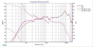
Mid FR: If you want to use a vented enclosure for the mid, go ahead, but I would go sealed. I modeled it in 4L. Looks like I chose to splice it at just a little lower spl as well. Other than that, they match perfectly.
Thank you for such a detailed analysis. Before I go back and re-run things I have a question around the Mid and Sealed Vs Ported. I picked ported purely based on the EBP and it falling well into the ported range. I can see that when I change the Mid to sealed it has a big effect on the group delay. So I guess my question is: should the group delay between the woofer and the mid be on a par or close or doesn't it matter? Based on WinISD, there would be a 10ms avg difference in delay if the Mid was sealed. Where as if its ported, the group delay is much closer.
Actually as a general rule, a vented design has more group delay than a sealed design but I've attached what WinISD shows for the Satori. Grey is vented and yellow is sealed, so the general rule applies here. Note however at what frequencies the differences happen anyways and then ask yourself when used as a mid in a 3-way, what frequencies end up not being used?
Also, the transient response is generally better in a sealed vs vented design. I'd probably go with a Q somewhere around .5 to .6 as that gives you some extra volume to add stuffing to better absorb the rear wave. Or to perhaps employ a physical strategy something like shown here (sans the vent) - http://www.humblehomemadehifi.com/download/Humble%20Homemade%20Hifi_Concertino.pdf. And as an aside, I would also consider doubling up the side and top walls to the mid enclosure too as I believe you have the extra volume available to play with and the added mass will make it harder to excite the mid chamber resonances.
Also, the transient response is generally better in a sealed vs vented design. I'd probably go with a Q somewhere around .5 to .6 as that gives you some extra volume to add stuffing to better absorb the rear wave. Or to perhaps employ a physical strategy something like shown here (sans the vent) - http://www.humblehomemadehifi.com/download/Humble%20Homemade%20Hifi_Concertino.pdf. And as an aside, I would also consider doubling up the side and top walls to the mid enclosure too as I believe you have the extra volume available to play with and the added mass will make it harder to excite the mid chamber resonances.
Attachments
- Status
- This old topic is closed. If you want to reopen this topic, contact a moderator using the "Report Post" button.
- Home
- Loudspeakers
- Multi-Way
- 3-Way Build Project - Woofer help