D'Appolito's book Testing Loudspeakers, 1998, Amateur Audio Press, section 3.6, shows the method of looking for impedance irregularities to find enclosure reflections and resonances (which is what a cabinet vibration produces in the output of the loudspeaker). That's a pretty simple test. You could also scan the Klippel procedures online for an equivalent procedure.
I don't believe that "knocking on the cabinet" is going to find what you really seek.
YMMV.
Chris
Yup, see post #4
I don't know that it exists. I scanned that out of the AES Journals 15 years ago…
dave
I found the Iverson paper you referred to in my AES Audio Anthology Vol.1 thru Vol. 25, 1953 to 1977. The paper was presented at the 42 convention of the AES in 1972. Iverson found that if panel resonances can be raised thru stiffening over 1000 hz, little vibration results. Duh, doesn't that follow????
You can get an accelerometer (look for ACH-01 or similar number from Measurement Specialties (carried by Digikey). Attach to a point on the cabinet, drive the speaker (i.e., measure from speaker terminals in to accelerometer out), measure with a sine sweep or MLS with HolmImpulse or REW. You can use paraffin to attach the accelerometer, not terribly well, but usable and (more important) removable.
Problems are in interpretation, look for frequencies more than just levels. The problem that comes up is that if a brace gets tested in a position where it is bracing near the accelerometer that position will appear to work better than others. The accelerometer position only sees one point on the cabinet
Problems are in interpretation, look for frequencies more than just levels. The problem that comes up is that if a brace gets tested in a position where it is bracing near the accelerometer that position will appear to work better than others. The accelerometer position only sees one point on the cabinet
Just let me know if anyone has an idea for a simple controlled knock test (or similar) so I could record the data, continue building the speakers and do the analysis later.
Yes: cut a ply disc that you can mount in your speaker hole, so that it can seal your cabinets airtight. Bolt a small, robust driver to the inside of this disc. Run a very loud sweep or noise through this. Record at 1m as if for a standard test. The perfect box would give 0dB output.
We are interested in the sound radiated by the cabinet and not really the deflection of the cabinet. At high frequencies it doesn't take much deflection to be as loud as the large deflections at low frequencies. Consider how small in size and deflection a tweeter membrane is compared to that of a large woofer. If the driver is stiffly bolted to the cabinet then Newton's 3rd law will ensure that whatever is required to get a driver to radiate sound at a particular level will be put into the cabinet in the same way at high and low frequencies. So no it does not follow given we are interested in reducing sound radiation.Iverson found that if panel resonances can be raised thru stiffening over 1000 hz, little vibration results. Duh, doesn't that follow????
What is different at high frequencies is that motion is no longer stiffness controlled like it is at low frequencies, damping is more effective, the mass of the drivers relative to the cones enables effective isolation, the higher frequency modes radiate less effectively, plus no doubt one or two other things I have missed which makes it substantially easier to do something about the vibration at higher frequencies than low frequencies.
Can you explain the logic behind this?Yes: cut a ply disc that you can mount in your speaker hole, so that it can seal your cabinets airtight. Bolt a small, robust driver to the inside of this disc. Run a very loud sweep or noise through this. Record at 1m as if for a standard test. The perfect box would give 0dB output.
If you tap the cabinet you are performing an impulse test. This injects a small amount of energy into the cabinet at a single point over a very short time. This is followed by the cabinet modes that have been excited decaying. If you measure the impulse response at, say, the listening position and take the Fourier transform you will see the modes that have been excited. If you tap somewhere else on the cabinet you will excite a different set of modes by different relative amounts. However, the frequency and degree of damping of the cabinet modes do not change and so by tapping all over the cabinet you can build up a picture of all the lowest frequency modes and how well they are damped.I just did the knock test because that's what I (and everyone else) do(es) with speaker enclosures. Then I thought it would be cool to have some objective data rather than just some subjective impression that is hard to interpret.
What you cannot get with this type of test is how much each mode will be driven by the drivers and internal air pressure. It is not the whole picture but it is still a significant amount of useful information and certainly enough to perform a meaningful comparison between your two cabinets.
You may need to change the listening position to see some modes because if the speaker is, for example, nodding side to side this will radiate sound like a dipole and there will be no effective radiation in the forward and rearward directions.
Perhaps the most significant issue with this type of test is that only a small amount of energy can be injected into the cabinet if the response is to remain linear (you won't get repeatable results if you bash hard). So there is not much signal and you will only pickup the lowest few modes with any degree of reliability. Nonetheless these tend to be the most relevant.
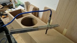
I made up a simple knock test set up that provided surprisingly consistent results using the partially built enclosures of my current loudspeaker project (see also attached photos):
I repeated this test about 10 times with each enclosure. Enclosures were placed at same positions (within 1mm precision). The microphone was not moved our touched when enclosures were exchanged. The replicate measurements were surprisingly consistent.
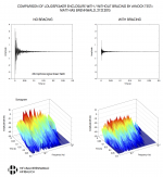
The results are shown in the attachment. The sonogram of the enclosure without braces clearly shows some resonances. With the bracing installed, the resonances are approximately 20 dB lower, and are hardly visible apparent in the spectrum. Overall, this seems to agree with the information I get from my ears: with the bracing, the sound is a short 'clunk'; without the bracing the sound is much louder, has a clear 'tone' to it, and it also seems to take longer to die away.
That was a fun experiment and I now know a bit better how to interpret the infamous knock test. But please don't use my results to abuse the knock test as the gold standard for enclosure resonance analysis (read posts 23 and 27!)
Now it's time to continue building those speakers!
- Enclosures are rectangular 22mm MDF boxes (238 mm wide, 251 mm deep, 591 mm high). Bracing was installed in first enclosure, bracing was not yet installed in the second enclosure (I will post a drawing of the enclosure and the bracing once it's complete).
- Enclosures were positioned with rear wall on bench, front baffle pointing upwards.
- The microphone was placed 8 mm above front baffle (nearfield measurement), 225mm from bottom of enclosure.
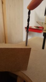
- I used a 5mm drill bit as 'hammer'. Held the bit in vertical position, 7 cm above front baffle of speaker enclosure. Then let drill bit fall on front baffle immediately below woofer hole (I used the wedge shown in the photo to get the 7 cm right in every experiment; I removed the wedge from the baffle before letting the bit fall down).
- The microphone signal was recorded and processed with MATAA at 44.1 kHz sampling rate. The microphone was a Beyerdynamic MM1 with custom CS Labs calibration data.
I repeated this test about 10 times with each enclosure. Enclosures were placed at same positions (within 1mm precision). The microphone was not moved our touched when enclosures were exchanged. The replicate measurements were surprisingly consistent.
The results are shown in the attachment. The sonogram of the enclosure without braces clearly shows some resonances. With the bracing installed, the resonances are approximately 20 dB lower, and are hardly visible apparent in the spectrum. Overall, this seems to agree with the information I get from my ears: with the bracing, the sound is a short 'clunk'; without the bracing the sound is much louder, has a clear 'tone' to it, and it also seems to take longer to die away.
That was a fun experiment and I now know a bit better how to interpret the infamous knock test. But please don't use my results to abuse the knock test as the gold standard for enclosure resonance analysis (read posts 23 and 27!)
Now it's time to continue building those speakers!
Attachments
Great job! You asked how it could be done and now worked out a way to do it DIY.
I did something similar some years back with a small test mic available from Meniscus Audio and ATB software. The SW generated a test signal similar to pink noise. The software produced a FR that started with hi dB at low freq. and gradually diminished as FR increased as you can see in the plots I attached. It was clear there was a resonance spike at 200 hz which I mitigated with a front to back brace.
Large Advent improvements - Advent - The Classic Speaker Pages Discussion Forums
Last edited:
We are interested in the sound radiated by the cabinet and not really the deflection of the cabinet. At high frequencies it doesn't take much deflection to be as loud as the large deflections at low frequencies. Consider how small in size and deflection a tweeter membrane is compared to that of a large woofer. If the driver is stiffly bolted to the cabinet then Newton's 3rd law will ensure that whatever is required to get a driver to radiate sound at a particular level will be put into the cabinet in the same way at high and low frequencies. So no it does not follow given we are interested in reducing sound radiation.
What is different at high frequencies is that motion is no longer stiffness controlled like it is at low frequencies, damping is more effective, the mass of the drivers relative to the cones enables effective isolation, the higher frequency modes radiate less effectively, plus no doubt one or two other things I have missed which makes it substantially easier to do something about the vibration at higher frequencies than low frequencies.
In the first paragraph you say at high freq. it doesn't take much deflection to be as loud as large deflections at low freq. Then, in the lower paragraph you say the higher freq. modes radiate less effectively. ?
I would hope we can agree that it's the woofer's energy that is the source of cabinet resonances that are of the most concern. Even Iverson implied that if you get the the resonances high enough with bracing, you've succeeded.
Stereophile's Atkinson's numerous speaker impedance plots show, in most cases some blips which are isolated to less than 1 kHz and he attributes those blips to a resonance. I don't recall him making any comments on HF resonances issues picked up during an impedance test.
Unlikely in a well designed cabinet. The radiation from a subwoofer cabinet is of little concern if it is stiff with the lowest resonance well above the passband. Similarly for a woofer cabinet although it is more difficult to achieve. Since energy doesn't move between frequencies in a linear system the woofer's energy becomes of no concern.I would hope we can agree that it's the woofer's energy that is the source of cabinet resonances that are of the most concern.
The lowest frequency resonances that are driven tend to be the loudest radiation from a cabinet and hence the focus for improvements (i.e. how to effectively damp them or perhaps isolate them). That's more likely to be midrange rather than woofer in high performance cabinets.
At high frequencies small cabinet motions can generate loud sound in the near field but the shorter wavelengths tend to mean that not too far away another part of the cabinet is generating equally loud sound in the near field but of opposite sign leading to a lot of cancellation in the far field. This is why the higher order modes tend to be more inefficient at radiating their energy to the far field than the lower order modes.
Something I've meant to try, but never got around to, is to take one of those transducers meant to be put onto blackboards or other thin surfaces (to turn them into loudspeakers of a sort), but mount them onto the BACK of the driver magnets in a speaker box. So you get the effect of a mass shaking in the speaker/box structure without directly shaking a cone. Ideally, no sound should come from the box.
Calibration would be an issue, though, it would be difficult to quantify any results done that way. But you might find which bracing or damping methods work better in a given box.
Calibration would be an issue, though, it would be difficult to quantify any results done that way. But you might find which bracing or damping methods work better in a given box.
That's a cool idea. I agree that calibration will not be straight forward, but the method is still useful to differentiate enclosure resonances from others (driver, acoustic, etc.). And it will certainly give accurate information of differences resulting from different bracing methods.
One problem with this is that it adds to the mass of the magnet and so will change the resonances associated with both the magnet mass/stiffness of driver frame and the driver mass/stiffness of baffle. Removing the magnet, adding the shaker and some ballast would perhaps be more representative. Another problem is that the driving forces from the internal air pressure is missing.Something I've meant to try, but never got around to, is to take one of those transducers meant to be put onto blackboards or other thin surfaces (to turn them into loudspeakers of a sort), but mount them onto the BACK of the driver magnets in a speaker box. So you get the effect of a mass shaking in the speaker/box structure without directly shaking a cone. Ideally, no sound should come from the box.
Calibration would be an issue, though, it would be difficult to quantify any results done that way. But you might find which bracing or damping methods work better in a given box.
A lot more understanding would come from an FE simulation. If you want a measurement based approach then mapping the cabinet motion with a vibrometer when in normal use would be more reliable.
Here's what I did when investigating cabinet wall vibrations:
Using a cheap clip-on piezo pickup intended for instrument use, I effectively measured the frequency response of the cabinet walls at different positions. The plan was to find the point(s) that showed up most of the vibrational modes, and then add bracing accordingly. This plan never came to fruition - I sold the cabinets.
Pickup attached to a screw in the handle:
Some data:
These were on 15" 2-way cabinets, with fairly minimal bracing. Since it was a live sound application, the acoustic output of the side panels was causing mic feedback where the frequency peaks are.
The woofer was EQ'd flat.
For anyone that's interested, I'd recommend getting a couple of those pickups - they're very cheap and provide lots of data when plugged into a laptop running REW.
Chris
Using a cheap clip-on piezo pickup intended for instrument use, I effectively measured the frequency response of the cabinet walls at different positions. The plan was to find the point(s) that showed up most of the vibrational modes, and then add bracing accordingly. This plan never came to fruition - I sold the cabinets.
Pickup attached to a screw in the handle:
An externally hosted image should be here but it was not working when we last tested it.
Some data:
An externally hosted image should be here but it was not working when we last tested it.
These were on 15" 2-way cabinets, with fairly minimal bracing. Since it was a live sound application, the acoustic output of the side panels was causing mic feedback where the frequency peaks are.
The woofer was EQ'd flat.
For anyone that's interested, I'd recommend getting a couple of those pickups - they're very cheap and provide lots of data when plugged into a laptop running REW.
Chris
I know this is an old topic, but is there anybody here that’s have too much money any time?
Motion Amplification
By using this technology one could really fine tune a cabinet based on the actual cabinet and not only in simulations.
Motion Amplification
By using this technology one could really fine tune a cabinet based on the actual cabinet and not only in simulations.
By using this technology one could really fine tune a cabinet based on the actual cabinet and not only in simulations.
This is not aimed at measuring the tiny deflections of speaker cabinets. A laser vibrometer is more appropriate, more accurate and is what has been used in industry to measure the motion of speaker cabinets for many years. Here is a student project that is doable by a keen DIYer if they have plenty of time and can lay their hands on a laser vibrometer. Scanning vibrometers can be expensive but single point ones can be found for around $1000 or so.
I've measured some cabinets using an accelerometer but what does it all mean? What's the goal? Complete absence of any and all vibrations? That's impossible and is it even desirable? Another test we did was 2 identical cabinets: one made of MDF and the other made of Corian. The Corian passed the knuckle test. It was like hitting a rock. But the finished speaker sounded better in the the MDF cabinet. The corian speaker sounded lifeless. So maybe some cabinet vibrations are OK ? I have found that in larger cabinets with too little bracing the bass sounds muddy. So in summary, use moderate bracing especially on larger panels and don't worry about it.
- Status
- This old topic is closed. If you want to reopen this topic, contact a moderator using the "Report Post" button.
- Home
- Loudspeakers
- Multi-Way
- Cabinet bracing: measurements?