Hi Nate,
I'm sorry, I didn't explain it well enough.
No you were clear, that's what I thought when I read it the first time......I've got a sim running now with the IB way behind the wg. We will see.
My wg profile is actually defined by just short of 100 steps. The first 1/2" of the throat is defined by about .008" steps in height, then they get larger, and then they get smaller at the mouth roundover. The data is all in standard units though....is that ok?
IIRC I've read that the conical throat section of the compression driver is accounted for in the LEM section of ABEC. I included that in my drawing but it's easy enough to take out.
Do you have any experience bringing in a mesh from another CAD program? Thanks for the help
Yes, I can see that absorption could be used to the same effect as a large radius, maybe even in a smaller space (although that is not obvious to me.) I am not sure what you mean by the difference between Acoustic Foam and reticulated foam. There are only two types of foam; open cell and closed cell, but both come in a wide range of pore sizes. Closed cell is not so good at absorption because the waves cannot penetrate into it. My foam is very large pore open cell for minimum absorption, but a much smaller cell size makes it much more absorptive. What would be best is a gradation of cells from large to small, but this cannot be done in a single block, it would take layering.
Any means of diminishing the mouth edge effects is good. In sharp edge square devices the diffraction is spread so wide that it does not have a strong far field effect, but it does still reflect the wave back down the horn creating a series of standing waves which can be seen in the plots.
A highly coherent waveguide like the OS or Nate's will have a pronounce effect from the mouth, but minimal standing waves and hence and overall smoother power response.
Sorry if I was unclear- typical foam used for acoustics IME is open cell and has a much smaller pores than your reticulated foam. The structure actually is a little different, as the small-cell open cell foam often retains SOME cell walls, where with the stuff you utilize, the cells are so large that the walls can be fully eliminated.
I'm using the smaller pore stuff- which is commonly used in packaging. The easy test for if it's a potentially useful foam for experimenting with is to try to blow air through it. If you can without blowing out your eardrums, it's worth a try. The density and poresize actually tends to be pretty consistent with this stuff, I rarely see closed-cell foams used in packaging (unless you're talking Styrofoam, a wholly different beast).
One note, if you're going to use salvaged foam (which opens up options as sometimes product packaging has angled and other useful shaped pieces) then be aware that it's likely flammable, and would give off highly toxic gas if it caught fire. Foams for acoustic panels are generally made a little differently to mitigate this issue, I don't recall the details.
The SEOS that I measured was good, but certainly not "polars can't be beat." I am not sure that there are a lot of the highly detailed polars like you and I have for our devices. I suspect that when compared one to one in the PolarMap program they would not come out on top. Also, the SEOS that I have seen have been very wide. The narrower the pattern, the harder it is to control.
OK "can't be beat" may be a bit of a stretch but all the data I've seen looks quite good. I've been thinking for a while that I'd like to get ahold of one of the DIY Sound Group speakers with a SEOS 12 or 15 and measure it for your database. I've even thought about buying SEOS 15 and the driver just to measure and study it as cheap as they are.
Nate, I would be interested to see the polars for the SEOS too. I am considering the SEOS 24 to replace my aging JBL 2380a biradial midhorn that people say produce distortion due to the diffraction slot, which I can't measure and the impulse looks clean. But that's another topic. Carry on ")
Sorry if I was unclear- typical foam used for acoustics IME is open cell and has a much smaller pores than your reticulated foam. The structure actually is a little different, as the small-cell open cell foam often retains SOME cell walls, where with the stuff you utilize, the cells are so large that the walls can be fully eliminated.
I'm using the smaller pore stuff- which is commonly used in packaging. The easy test for if it's a potentially useful foam for experimenting with is to try to blow air through it. If you can without blowing out your eardrums, it's worth a try. The density and poresize actually tends to be pretty consistent with this stuff, I rarely see closed-cell foams used in packaging (unless you're talking Styrofoam, a wholly different beast).
That is not my understand from the foam guys. There are only open cell and closed cell (what you call reticulated is the same thing. "Reticulated" is the process of opening the cells.) All foams start out basically close cell. To get open cell from closed cell you have a secondary process that takes energy to blow out the cells walls - a small explosion from cell to cell. This means that open cell is always more expensive. This also means that the vast majority of packaging foam is closed cell since open cell has no benefit in that application. So unless you are paying a premium for the foam that you know for sure is open cell then its closed cell. I have had this arguments several times with people who use foam. They usually say it is open cell and it usually is closed cell. If you cannot poor water straight through it then it is close cell.
Test it!
Nate, to replace my aging JBL 2380a biradial midhorn that people say produce distortion due to the diffraction slot, which I can't measure and the impulse looks clean. But that's another topic. Carry on
The distortion from the diffraction slot is a linear distortion and won't show up as a nonlinear distortion. It can be hard to measure since the diffractions and reflections are small and the impulse is a linear thing - small deviations are hard to see. If you have a very hi-res polar response then you will see these as arcs of polar disruption, or resonances - depends on the path.
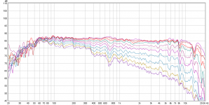
Mitch - this isn't my data but it was taken by one of the DIYSG designers (mtg90). Outdoors I think and 0-90 in 10deg steps. BMS coax driver which you can see at 6-7khz. I believe the wg is in a cabinet with the woofer.
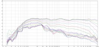
The second plot is also a SEOS 24 with a Radian 951Be. I'm not sure how they were measured but it's 0-180 in 10 deg steps. The wg is freestanding here, which might explain some of the differences (namely the issue at 700hz in the first plot), and I wonder if this is a smoothed in-room measurement. Different designer (RyanCo) here and they are both obviously finished speakers crossing around 400hz. Both pics were pulled from AVS.
The second plot is also a SEOS 24 with a Radian 951Be. I'm not sure how they were measured but it's 0-180 in 10 deg steps. The wg is freestanding here, which might explain some of the differences (namely the issue at 700hz in the first plot), and I wonder if this is a smoothed in-room measurement. Different designer (RyanCo) here and they are both obviously finished speakers crossing around 400hz. Both pics were pulled from AVS.
Attachments
Earl, thanks for the insight. My current speakers with the 2380a clones (and QSC waveguide on top) weigh in at 130 lbs. When I change them out, I will measure/collect the data for your Polar Map software.
Nate, thanks for the info. I will check over at AVS.
Back to your Mini-Synergy horn.
Maybe I missed it, passive or digital XO? If passive XO, are you thinking of doing something similar to what bwaslo has (amazingly) achieved with his
http://www.diyaudio.com/forums/mult...nergy-speakers-doing-almost-linear-phase.html
FYI, the NS-15 holds just about the same phase linearity as is being shown here for the synergy. My point is that it can be done with more traditional designs, its just not that common.
I have always wondered what a polar map of phase would look like. Could be interesting, but somewhat difficult to do if there is phase wrapping.
PS Mitch, it was our discussions of phase that prompted me to check my designs to see what it looked like. I knew that since the impulse response was very compact that it wouldn't be to bad, but I was surprise just how linear it was. This was probably more coincidental than intended, but I'm not complaining.
Last edited:
I would imagine so. When using the rePhase software it allows you to unwrap the phase and see as much as +/-1440 degrees. It's an interesting view of things.Could be interesting, but somewhat difficult to do if there is phase wrapping.
Earl, thanks for the insight. My current speakers with the 2380a clones (and QSC waveguide on top) weigh in at 130 lbs. When I change them out, I will measure/collect the data for your Polar Map software.
Nate, thanks for the info. I will check over at AVS.
Back to your Mini-Synergy horn.
Maybe I missed it, passive or digital XO? If passive XO, are you thinking of doing something similar to what bwaslo has (amazingly) achieved with his
http://www.diyaudio.com/forums/mult...nergy-speakers-doing-almost-linear-phase.html
I'm using a digital xo (JRiver). I've never done a passive xo before, and I've been thinking about doing one just to simplify and eliminate an amp channel. It seems quite complex with the delay needed. Since this is just a background/pa type speaker for now I think I'll forgo the complexity of keeping the linear phase. It might be a fun experiment to try though.
FYI, the NS-15 holds just about the same phase linearity as is being shown here for the synergy. My point is that it can be done with more traditional designs, its just not that common.
I have always wondered what a polar map of phase would look like. Could be interesting, but somewhat difficult to do if there is phase wrapping.
PS Mitch, it was our discussions of phase that prompted me to check my designs to see what it looked like. I knew that since the impulse response was very compact that it wouldn't be to bad, but I was surprise just how linear it was. This was probably more coincidental than intended, but I'm not complaining.
Something good to include in the ad copy for the NS-15
. I've never really given it any thought for a regular speaker with vertically offset drivers. Pretty much I just shoot for an acoustic xo target (typically LR6 with waveguides) and call it a day. I might look into this with my main speakers over the long weekend coming up.That said, I don't hear anything different in my main system with an FIR correcting the phase for the wg to woofer xo. Maybe what I'm listening to is so poorly recorded to begin with that there's really no benefit? From what I've read and heard from others the main benefit to phase correction comes the low end of sealed and br woofers.
I believe the old TEF systems could show phase/magnitude on a polar plot (a delayed response looks like a corkscrewed trace, kind of neat but I don't know what the advantage might be).
I've done a number of phase unwrapping routines. There isn't any way to guarantee correctness without making some assumptions about the system being measured, but the most reliable algorithm I've found is:
1) remove whatever fixed delay is needed to minimize the number of "wraps".
2) start at some low frequency where phase is assumed to reliable, and proceed upward in frequency. If the change in phase is more than 90degrees then subtract 360 degrees (and if more negative than -90degrees add 360 degrees) at each frequency point there and above. (That assumes that changes of more than 90degrees are caused by the phase wraps). You may accumulate multiples of 360degrees to add as you get higher in frequency, so keep track of the value.
3) apply back the fixed delay from step 1.
Another approach (a little easier to program) is to start at some trustworthy LF (away from measured phase changes that change from + to - or opposite), go to the next higher point and find the delay between the previous two points =
-deltaPhase/(360*deltaFreq).
On going to each next point, assign the phase value of (measuredPhase+N*360) using the value of N which gives the closest to the delay value (with its just previous frequency) as you determined from the previous pair of frequency points.... IOW, select for least abrupt delay changes between adjacent points.
Sharp resonances with sparse frequency points will mess up either approach...
Last edited:
I'm using a digital xo (JRiver). I've never done a passive xo before, and I've been thinking about doing one just to simplify and eliminate an amp channel. It seems quite complex with the delay needed. Since this is just a background/pa type speaker for now I think I'll forgo the complexity of keeping the linear phase. It might be a fun experiment to try though.
Something good to include in the ad copy for the NS-15
That said, I don't hear anything different in my main system with an FIR correcting the phase for the wg to woofer xo. Maybe what I'm listening to is so poorly recorded to begin with that there's really no benefit? From what I've read and heard from others the main benefit to phase correction comes the low end of sealed and br woofers.
I use JRiver Convolution to host FIR filters generated from Acourate. My 3-way with 15" in large sealed cab and mid/high freq horns are time aligned, frequency and excess phase corrected. Here is a measure at the LP some 9ft away using REW's default FDW setting and psychoacoustic smoothing:
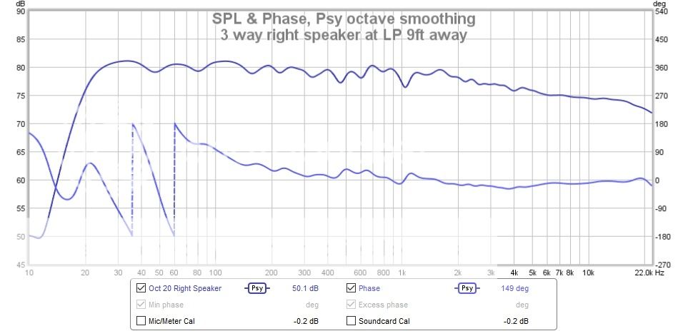
I have a couple of phase wraps in the low end due to a room mode at 56 Hz and looking into fixing that.
For me, time aligned or phase coherent or whatever you want to call it, becomes point source sound. Subjectively means I can't tell where the sound is coming from. I really like that illusion.
Nate, looking forward to seeing how this all works out for you as I am considering ditching my traditional horns. I like constant directivity and enjoy my QSC waveguide and BMS 4540ND treble compression driver, but finding a capable 2" midrange driver and constant directivity waveguide combo to cover 500Hz to 5 kHz midrange that is SOTA seems pretty hard to put together (and $$'s)... Hence why I am liking yours, bwaslos, and xrk's synergy projects.
I don't know how it's done, and I don't know that it's done correctly. I make the measurements in HOLM, then export a text file for rePhase to use. If I chose to let HOLM wrap the phase on export, then rePhase can be made to unwrap it. Conversely, if the HOLM export is unwrapped, then it has to be wrapped in rePhase to look right.Unwrapping the phase is not a trivial process. I've not programmed it myself and it seems complicated. If someone had a simple algorithm I might give it a try.
Not really sure what's going on there, but I'll look into it.
I found that to be true in a mid/tweeter measurement with a bad reflection. The unwrapped phase didn't make any sense.Sharp resonances with sparse frequency points will mess up either approach...
For me, time aligned or phase coherent or whatever you want to call it, becomes point source sound. Subjectively means I can't tell where the sound is coming from. I really like that illusion.
Nate, looking forward to seeing how this all works out for you as I am considering ditching my traditional horns. I like constant directivity and enjoy my QSC waveguide and BMS 4540ND treble compression driver, but finding a capable 2" midrange driver and constant directivity waveguide combo to cover 500Hz to 5 kHz midrange that is SOTA seems pretty hard to put together (and $$'s)... Hence why I am liking yours, bwaslos, and xrk's synergy projects.
Yeah that's a nice response. The FDW in REW is pretty cool. TBH I haven't spent a whole lot of time getting the FIR filter optimized. Maybe I'll do that yet this winter. My main system is kinda similar: the wg from this thread (NOT "Synergized"), a 15" passive resistance mid, and a sealed 15 woofer.
I heard a system with the big SEOS 24 and BMS coax. It was still in progress as far as the eq/xo goes but it was quite promising. This Synergy horn is a step in the right direction and I'll be spending the winter designing a big one to be built in the spring.
For me, time aligned or phase coherent or whatever you want to call it, becomes point source sound. Subjectively means I can't tell where the sound is coming from. I really like that illusion.
Nate, looking forward to seeing how this all works out for you as I am considering ditching my traditional horns. I like constant directivity and enjoy my QSC waveguide and BMS 4540ND treble compression driver, but finding a capable 2" midrange driver and constant directivity waveguide combo to cover 500Hz to 5 kHz midrange that is SOTA seems pretty hard to put together (and $$'s)... Hence why I am liking yours, bwaslos, and xrk's synergy projects.
Mitch, I am quickly becoming convinced that phase linearity is important, ever since I read Dr. Griesingers paper on this subject. I don't see it as important at LFs for just the reasons that he mentions. He claims, and I agree, that 700 - 7 kHz is the most critical. And I also agree that this yields the point source sound that everyone talks about the Synergy having. This is exactly the way I would describe the sound of my speakers. They all have compact impulse responses, minimum phase variations above a certain point, well controlled polar responses, and very smooth listening axis response. My guess is that they would all sound about the same - head and shoulders above most other speakers, but very similar within themselves. I will admit that the synergy has more potential for higher output than any of my speakers - scaling up the power would be easy. Not so easy with my designs.
If I were you, I would punt on the 2" midrange driver and just go with a great 1" driver like the DE500. Why do you need all that power? (2") This is a home system right?
Oh and Earl - what would be the point to doing a polar plot of the phase?
I would look for a consistent phase variation with angle just as I look for the same in magnitude. If phase is important to the direct signal then it has to also be important for the reflected ones.
- Status
- This old topic is closed. If you want to reopen this topic, contact a moderator using the "Report Post" button.
- Home
- Loudspeakers
- Multi-Way
- Mini-Synergy Horn Experiment