Wave-front shape and impulse response: spherical, cylindrical, plane-wave
If I am not mistaken, a theoretical point-source, infinite line-source and infinite plane source are all capable of perfectly reproducing an impulse. I always thought that the 'impulse train' you see when you measure a real-world line-array is caused by practical limitations in driver size and spacing. However, now I'm not so sure.
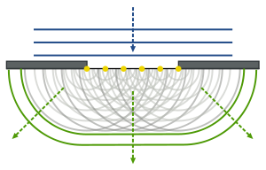
According to the Huygens principle any point on a wave-front can be represented by imagining that on every point on the wave-front there is a point-source that emits a spherical wavefront. The complex sum of this infinite number of point-sources describes how the initial wave propagates. This means that a line-source and a plane-source can be modeled as an infinite number of point-sources.
From wikipedia
I think I understand how this works with continuous signals such as a sine-wave. But what happens when we send an impulse to for instance a line-source? If the wave-front truly is cylindrical in shape, I imagine the impulse-response would be perfectly reproduced. But if the wave-front is the result of an infinite number of point-sources as per Huygens, I would expect to see a first relatively strong impulse followed by an infinite number of ever smaller impulses. Is this really what happens in the case of the theoretical ideal line source and plane source?
If I am not mistaken, a theoretical point-source, infinite line-source and infinite plane source are all capable of perfectly reproducing an impulse. I always thought that the 'impulse train' you see when you measure a real-world line-array is caused by practical limitations in driver size and spacing. However, now I'm not so sure.
According to the Huygens principle any point on a wave-front can be represented by imagining that on every point on the wave-front there is a point-source that emits a spherical wavefront. The complex sum of this infinite number of point-sources describes how the initial wave propagates. This means that a line-source and a plane-source can be modeled as an infinite number of point-sources.
An externally hosted image should be here but it was not working when we last tested it.
From wikipedia
I think I understand how this works with continuous signals such as a sine-wave. But what happens when we send an impulse to for instance a line-source? If the wave-front truly is cylindrical in shape, I imagine the impulse-response would be perfectly reproduced. But if the wave-front is the result of an infinite number of point-sources as per Huygens, I would expect to see a first relatively strong impulse followed by an infinite number of ever smaller impulses. Is this really what happens in the case of the theoretical ideal line source and plane source?
Last edited:
I would expect to see a first relatively strong impulse followed by an infinite number of ever smaller impulses.
Is this really what happens in the case of the theoretical ideal line source and plane source?
Yes, only a point source would give a good impulse response. Sine wave frequency response tests
would just show directivity, though.
Last edited:
Could you give an example of what a good impulse would look like?
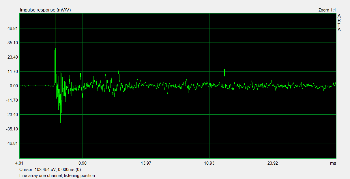
Because the impulse of my straight line array looks pretty normal to me:

By the way, that flying line at the top is the STEP response. Wiggles are probably comb filtering, as that is very real. Distance between speakers for this array: 85.5 mm, 25 drivers.
Time difference between out most driver arrival at ear vs the driver at ear height 0.6 ms.

21.6 cm time difference to ear at 3 meter distance.
Because the impulse of my straight line array looks pretty normal to me:
By the way, that flying line at the top is the STEP response. Wiggles are probably comb filtering, as that is very real. Distance between speakers for this array: 85.5 mm, 25 drivers.
Time difference between out most driver arrival at ear vs the driver at ear height 0.6 ms.
21.6 cm time difference to ear at 3 meter distance.
Could you give an example of what a good impulse would look like?
PLUSMUSIC US | Sound System Design
if the wave-front is the result of an infinite number of point-sources as per Huygens, I would expect to see a first relatively strong impulse followed by an infinite number of ever smaller impulses. Is this really what happens in the case of the theoretical ideal line source and plane source?
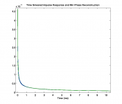
Your expectation isn't far from the truth. Considering a line array of infinite length made up of an infinite number of point sources, with each point source producing a flat frequency response, the impulse response at the listening position will consist of a step up followed by a decay that asymptotically approaches 0 but never quite reaches it.
However, despite the flat frequency response of the point sources, the frequency response of the array at the listening position will have a low-pass response with a slope of -3dB per octave. Equalization back to a flat frequency response will change the impulse response, and you will no longer have the step-decay scenario I described earlier. What you end up with will depend on your method of equalization, I suppose. I haven't looked too deeply into that, but it looks like Wesayso has achieved nice results.
Last edited:
Yes, only a point source would give a good impulse response. Sine wave frequency response tests
would just show directivity, though.
I'm not sure I understand. A point source has no directivity.
I'm not sure I understand. A point source has no directivity.
Right, a line or plane source would show directivity, not a point source.
Your expectation isn't far from the truth. Considering a line array of infinite length made up of an infinite number of point sources, with each point source producing a flat frequency response, the impulse response at the listening position will consist of a step up followed by a decay that asymptotically approaches 0 but never quite reaches it.
However, despite the flat frequency response of the point sources, the frequency response of the array at the listening position will have a low-pass response with a slope of -3dB per octave. Equalization back to a flat frequency response will change the impulse response, and you will no longer have the step-decay scenario I described earlier. What you end up with will depend on your method of equalization, I suppose. I haven't looked too deeply into that, but it looks like Wesayso has achieved nice results.
I wanted to come back to this point, because I still see a lot of posts associating a "time smear" with line arrays.
Here's a picture that roughly represents the impulse response I was describing for an array of elements each with a flat frequency response (and minimal or no phase distortion). The closest speaker impulse arrives first, and is the loudest. Subsequent arrivals are delayed and attenuated.
An externally hosted image should be here but it was not working when we last tested it.
As mentioned, this results in a low-pass effect at the listening position when the response to all the elements is taken together. In order to correct for that, the response needs to be shaped. A high pass filter needs to be applied to counteract the low pass effect of the line array element combination.
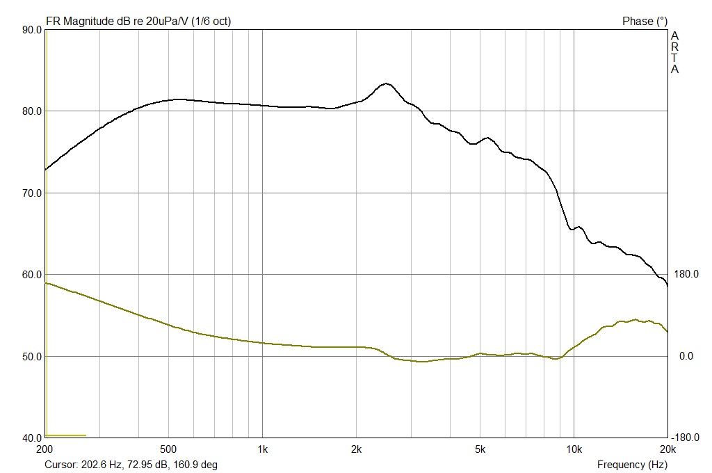
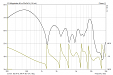
Here's an example of a sloping high pass response:
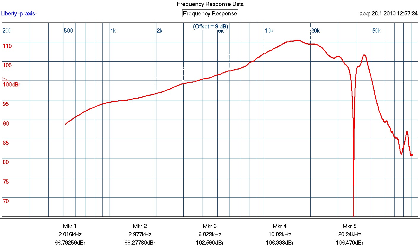
Ignore the stuff above 20 khz.
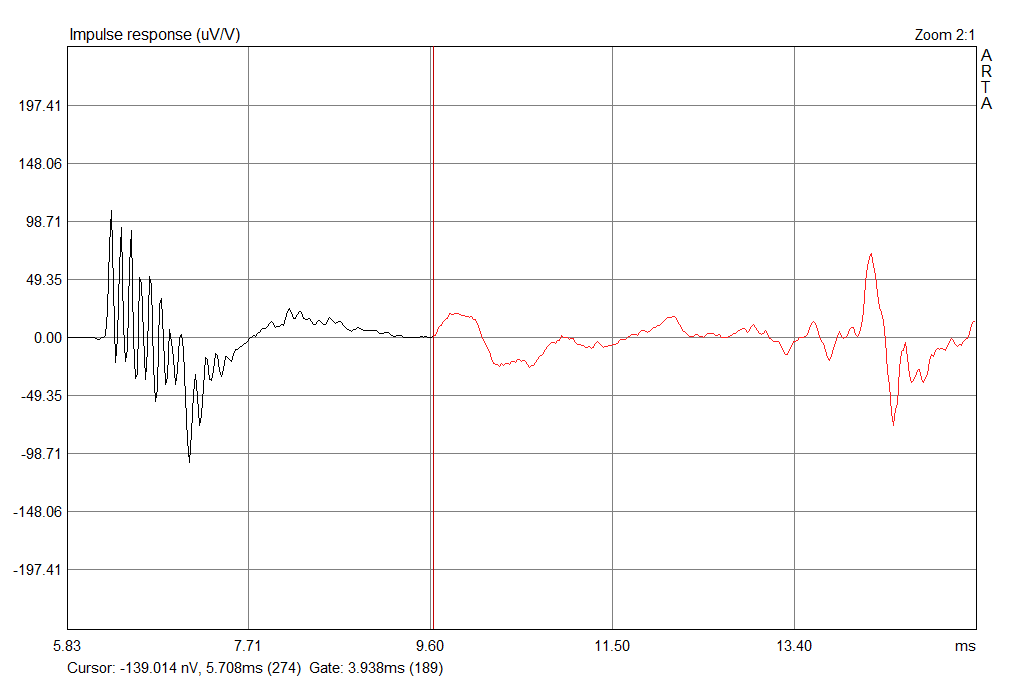
Here's the associated impulse response:
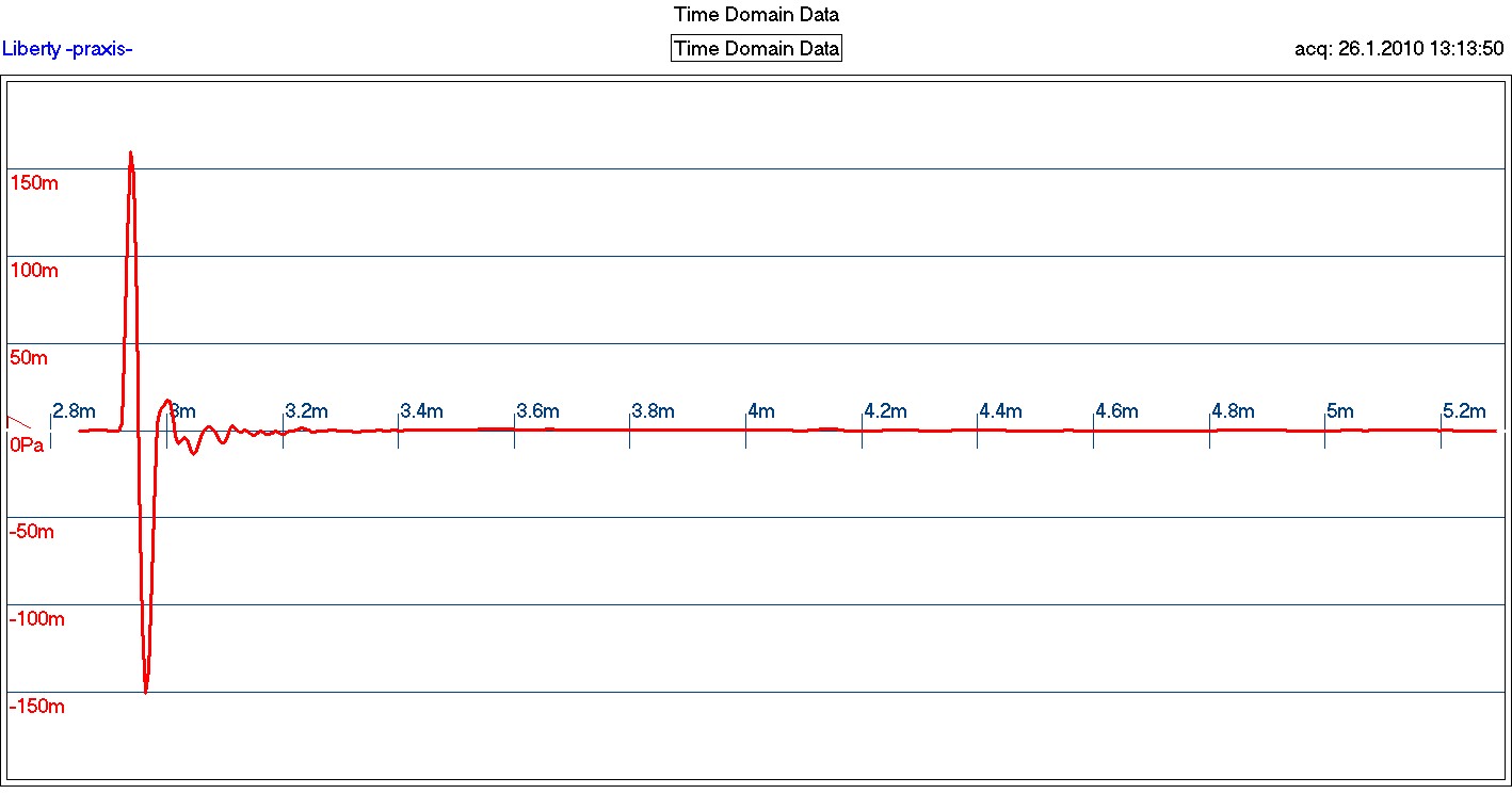
Now let's re-imagine our line array impulse response when each element is high-pass filtered to offset the low-pass system response. If each element is producing an impulse response like that shown above, then the positive spike of each subsequent arrival is offset by the negative spike of the prior arrival. This can give the effect of a nice clean impulse on the listening axis, with no "time smear".
Sorry I don't have the time to post simulations at this time... I have other things going on.
Now let's re-imagine our line array impulse response when each element is high-pass filtered to offset the low-pass system response. If each element is producing an impulse response like that shown above, then the positive spike of each subsequent arrival is offset by the negative spike of the prior arrival. This can give the effect of a nice clean impulse on the listening axis, with no "time smear".
Thanks bbutterfield. So basically what you are saying, is that a line-array is still a minimum-phase system and its smeared impulse response can be fixed simply by means of a minimum-phase filter. This filter fixes both the transfer function, as well as the impulse. Very interesting! I think it makes sense.
Sorry I don't have the time to post simulations at this time... I have other things going on.
If you can find the time, I'd still love to see it. What software do you use to run those sims?
A line array is only minimum phase at 0°. Under higher vertical angles where the side lobes occur (caused by driver distance) there is no minimum phase behaviour anymore.
0°:
60° vertical:

There are 8 impulses (from 8 drivers) caused by the side lobes above 10 kHz. The phase response shows a completely different behaviour than at 0°. So it is not minimum phase overall.
- More measurements
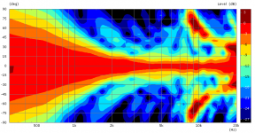
Vertical Directivity:

0°:
60° vertical:
There are 8 impulses (from 8 drivers) caused by the side lobes above 10 kHz. The phase response shows a completely different behaviour than at 0°. So it is not minimum phase overall.
- More measurements
Vertical Directivity:
Attachments
Last edited:
FoLLgoTT, what is it about the spectrum and impulse of the short line array at 60 degrees that makes you think it's not minimum phase? Those nulls in the frequency response don't actually hit 0 (-inf on log scale).
I don't see anything about them that makes me think they're not minimum phase. I ran a matlab/octave simulation to check, and performed a minimum phase reconstruction on the impulse and found that it matched the original.
A system can be minimum phase and still create a time smear (though the frequency response wont be flat) . These issues are separate, and we ought to discuss them as such.
Last edited:
I don't see anything about them that makes me think they're not minimum phase. I ran a matlab/octave simulation to check, and performed a minimum phase reconstruction on the impulse and found that it matched the original.
Hmm, maybe you are right. Every angle may be minimum phase for its own. Although the phase response differ much between all angles.
If this is true, forget my last post.
")
I wanted to come back to this point, because I still see a lot of posts associating a "time smear" with line arrays.
Now let's re-imagine our line array impulse response when each element is high-pass filtered to offset the low-pass system response. If each element is producing an impulse response like that shown above, then the positive spike of each subsequent arrival is offset by the negative spike of the prior arrival. This can give the effect of a nice clean impulse on the listening axis, with no "time smear".
Thank you for your post.
Adding the high pass corrects the innate line source "smear"? So the high pass filter phase response flattens the composite array phase response? Is my thinking wrong here?
Thank you for your post.
Adding the high pass corrects the innate line source "smear"? So the high pass filter phase response flattens the composite array phase response? Is my thinking wrong here?
Your thinking is correct. With a line array of minimum phase sources, a minimum phase high-pass filter that flattens the total response at the listening position will also improve the phase response and correct the time smear (at the listening position).
With practical line arrays, the frequency response at other positions will not be flat, and time smear will not be corrected. The more the implementation differs from the theoretical (height, driver spacing, etc) the greater the problems will be.
Also, I'm not entirely sure what methods are typically used to flatten the system frequency response, and how closely they match the theoretical minimum phase fix.
I have never built a line array, nor do I plan to. If I desired good sound in the back of a room, then a floor-to-ceiling line array would likely be my choice. For a listening position less than 20 feet away from the speakers, I think there's a better alternative.
bbutterfield, my own floor-to-ceiling array constitutes of thirty 3" full-range drivers. I've EQ'ed it as best I can, but the step response nevertheless is similar to the one you posted earlier.


My experience is that it is very difficult to get accurate in-room measurements of the array. You simply see a lot of interference, which results in a smeared impulse response as well as a very ragged amplitude response with lots of peaks and dips. Move the mic just slightly and the response at higher frequencies tends to change a lot. What I do, is I take lots of measurements and average them. I EQ based on this average.
Earlier you said you could run some simulations. I'd love for you to do that. Would you please show the impulse response of a near-ideal array (with infinite or very long length and with densely packed point-sources), both with and without 3dB/oct. highpass? I'd also very much like to see what the effects of an increase in driver spacing are. I doubt he impulse response of a real-world line-array such as my own can be fixed by means of a simple high-pass filter.
Last edited:
bbutterfield, my own floor-to-ceiling array constitutes of thirty 3" full-range drivers. I've EQ'ed it as best I can, but the step response nevertheless is similar to the one you posted earlier.
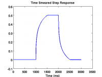
If what you've posted is a step response, rather than an impulse response, I think the onset looks very nice, with no sign of time smearing. Band limited step responses tend to look like what you've posted, with a jump up, and then a decay back down. If you had a system with flat response down to 0 hz, then it wouldn't decay.
If you had a time smeared step response, it wouldn't jump up all at once, it would slew up as the more distant drivers added their pressure after some delay.
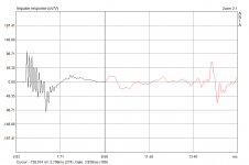
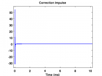
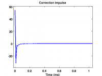
I have created 4 pictures that I am attaching below relating to a very tall, very densely packed line array.
I have included the impulse response (with minimum phase reconstructed impulse overlay), the step response, and the correction impulse response at 2 different zoom levels. If I convolve the impulse response with the correction impulse, I get a perfect dirac.
I hope these are informative.
Attachments
Your thinking is correct. With a line array of minimum phase sources, a minimum phase high-pass filter that flattens the total response at the listening position will also improve the phase response and correct the time smear (at the listening position). .........
Thank you again for your posts and confirmation. I think I can now mesh the theory with my present understanding and experience. Most helpful.
If what you've posted is a step response, rather than an impulse response, I think the onset looks very nice, with no sign of time smearing. Band limited step responses tend to look like what you've posted, with a jump up, and then a decay back down. If you had a system with flat response down to 0 hz, then it wouldn't decay.
If you had a time smeared step response, it wouldn't jump up all at once, it would slew up as the more distant drivers added their pressure after some delay.
You are right of course, I accidentally posted the step response instead of the impulse response. The impulse response of your simulation looks very similar to the step response of my arrays.
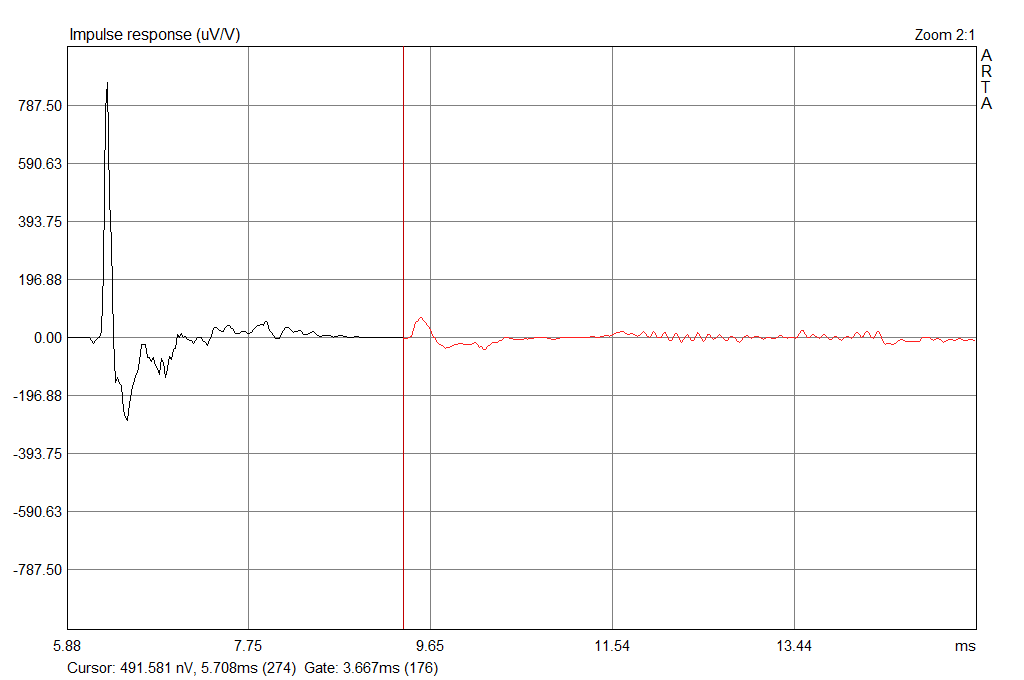
This is the in-room impulse response of my line-arrays:
I have created 4 pictures that I am attaching below relating to a very tall, very densely packed line array.
I have included the impulse response (with minimum phase reconstructed impulse overlay), the step response, and the correction impulse response at 2 different zoom levels. If I convolve the impulse response with the correction impulse, I get a perfect dirac.
I hope these are informative.
Very! Thank you very much. I'm assuming the smeared impulse response of my line-arrays is caused by real-world limitations such as non-infinitesimal driver spacing and a not perfectly reflecting floor and ceiling. Do you agree?
- Status
- This old topic is closed. If you want to reopen this topic, contact a moderator using the "Report Post" button.
- Home
- Loudspeakers
- Multi-Way
- Wave-front shape and impulse response: spherical, cylindrical, plane-wave