I'm looking to modify the Xover frequency of some Accuphase F-25 Xover boards.
The F-25 uses Gaussian filters realised using Generalised Immitance Converters (GICs).
We've tried comparing the RC values on different boards and adjusting accordingly but are getting confusing results on board modified for 20Hz low pass which seems to have become "all-pass".
Can anyone give me any advice please?
Thanks!
...The F-25 uses Gaussian filters realised using Generalised Immitance Converters (GICs)....
Gaussian filters are not common, the data in Self's book looks incorrect. I started a thread on this a while back.
I can try to help if you can post the circuit, or link.
Best wishes
David
I see that you have already found that thread.
Sorry I missed your post.
Last edited:
I'm not having much luck finding a circuit diagram.
What I have is a paper on GIC filters (http://www.tij.co.jp/jp/lit/an/sbaa001/sbaa001.pdf) and measured values from some boards.
Each board contains components for LP and HP. I have attached the Accuphase block diagrams .
For example on the 1200Hz board each of these components goes out to the connector
R1 39K, R3 3.88K, R5 3.87K, R7 3.88K, R9 2.36K, R11 1.76K, R13 7.4K, R15 14.82K
C1 23.9n, C3 24.2n, C5 24.4n, C7 24.1n, C9 23.8n
R17 10R3 in series with C11 23.9n
Tried taking a guess as to the correspondence between the measured values and the Accuphase diagrams.
I tried using the approach described in the paper to try to derive the values for a 1200Hz board starting from the LC for a Gaussian filter. Didn't come up with values that matched though.
Then just tried scaling based on comparing boards but the 20Hz board we produced seems to be acting like an all pass.
Regards, Dave.
Attachments
...Each board contains components for LP and HP. I have attached the Accuphase block diagrams .
For example on the 1200Hz board each of these components goes out to the connector
R1 39K, R3 3.88K, R5 3.87K, R7 3.88K, R9 2.36K, R11 1.76K, R13 7.4K, R15 14.82K
C1 23.9n, C3 24.2n, C5 24.4n, C7 24.1n, C9 23.8n
R17 10R3 in series with C11 23.9n...
Theoretical Gaussian filter is not a rational polynomial function so can only be approximated AFAIK.
So I will have a look at the values and reference and see if I can work out what they have implemented, more later.
Maybe we can trace the circuit, where are you in Aus?
Best wishes
David
...
For example on the 1200Hz board each of these components goes out to the connector
R1 39K, R3 3.88K, R5 3.87K, R7 3.88K, R9 2.36K, R11 1.76K, R13 7.4K, R15 14.82K
C1 23.9n, C3 24.2n, C5 24.4n, C7 24.1n, C9 23.8n
R17 10R3 in series with C11 23.9n
...to the correspondence between the measured values and the Accuphase diagrams.
You have more than one frequency board?
Can you compare the values to see which components scale as you expect?
Otherwise you may have to trace the circuit to determine which component corresponds to what.
Pity you are in Perth, a little far for me to look first hand.
Presumably all the values in your post are measured?
And all the capacitors are intended to be identical.
If they are actually marked with these not-quite-equal values then it would be attempt to compensate for non-ideality, seems unlikely.
Best wishes
David
I'll gather together all the values for all of the boards and get back to you. They are indeed measured.
Complicating things there are components for 12db, 18dB and 24db slopes on each board.
Given all the components are individually and separately connected to the edge connector, tracing the circuit would mean working on the "motherboard".
Complicating things there are components for 12db, 18dB and 24db slopes on each board.
Given all the components are individually and separately connected to the edge connector, tracing the circuit would mean working on the "motherboard".
Gathered values from a number of boards and did some spreadsheeting and also learned how to use LTspice a bit when I managed to get hold of a circuit diagram.
I was able to extrapolate from the existing component values and shown in the attached spreadsheet.
The LTspice simulation of the low pass filter was OK but haven't been able to get the high pass filter right yet.
Still testing the 20Hz module.
I was able to extrapolate from the existing component values and shown in the attached spreadsheet.
The LTspice simulation of the low pass filter was OK but haven't been able to get the high pass filter right yet.
Still testing the 20Hz module.
Attachments
Sorry not to reply earlier, my LTSpice machine is down and replacement has been slow, can't even unzip a file at the moment.
So I will comment a bit later or you can post the ASC as a PDF picture and unzip the values into simple text if you prefer not to wait.
Best wishes
David
So I will comment a bit later or you can post the ASC as a PDF picture and unzip the values into simple text if you prefer not to wait.
Best wishes
David
You might ask 'wintermute' as he's done quite a bit of work...
Not as far as I can find, no post from "wintermute" with text "F-25", "F25" or "Accuphase".
Do you have a link?
Best wishes
David
... 'The Synergy "Active" Crossover'
Thank James, I found the thread once I had the title, and it looks of interest.
Now to read it properly while I wait for my new LTSpice machine.
Best wishes
David
Funny that this particular subtopic is mostly Australian, but inconvenient that no one is in the same city
Last edited:
Thanks Dave and James. I'll read that thread too.
We have our 5-way Accuphase F-25 Xover with a 20Hz module working now. I'm suspecting a wiring error for our initial problem - lots of interconnects with 10 amps!
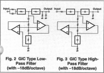
Out of interest I'm attaching the circuit diagrams for the 1200Hz 18dB low and high-pass filters.
For the 1200Hz 18dB low pass filter 3dB points were predicted 1242Hz, measured 1300Hz.
For the 1200Hz 18dB high-pass filter 3dB points were predicted 1875Hz, measured 1175Hz.
The predicted 3dB point of the HP filter was way off.
Other thing I noticed when summing the outputs was that there was a 180 difference in phase at the crossover points.
We have our 5-way Accuphase F-25 Xover with a 20Hz module working now. I'm suspecting a wiring error for our initial problem - lots of interconnects with 10 amps!
Out of interest I'm attaching the circuit diagrams for the 1200Hz 18dB low and high-pass filters.
For the 1200Hz 18dB low pass filter 3dB points were predicted 1242Hz, measured 1300Hz.
For the 1200Hz 18dB high-pass filter 3dB points were predicted 1875Hz, measured 1175Hz.
The predicted 3dB point of the HP filter was way off.
Other thing I noticed when summing the outputs was that there was a 180 difference in phase at the crossover points.
Attachments
- Status
- This old topic is closed. If you want to reopen this topic, contact a moderator using the "Report Post" button.
- Home
- Loudspeakers
- Multi-Way
- Accuphase F-25 active crossover board mod help