This is really cool.
I'd be interested to try out your stereo recordings some time. Could you upload them to Dropbox and share them here?
TIA
Chris
Thank you
")
I didn't record the signal, it was just a direct feed. I do want to make some recordings and put them online somewhere but I have to find the time and there has to be no wind. The idea is to record the scene using different methods and also provide a drawing of the setup with distances and angles.
regards,
Gerrit
Gerrit,
Congrats on the OB built.
I am working on a very similar looking project, but there are also some major differences.
There are many great things about your speakers, but this is a discussion board, so I will also mention the weaknesses I see.
First the vertical orientation of the drivers and the C/C distance (okay, you mention this yourself too). the C/C distance between your T and M is greater than a wavelength. and between your M and lower W is greater than 1/2 wavelength.
Second is the choice of two 10" Ws and their mounting. I would have gone for a single 15" with no baffle (nude swinging or magnet mount). This would have been cheaper, more practical and probably sonically superior too.
And now my plans:
B&G Neo8S high pass 800hz (felt/foam treated to improve vertical dispersion)
8" vintage Seas 200-800hz
15" GPA 416-8B 50-200hz
all no baffle (nude swinging)
all DSP active
add ripole sub later
I'm duly impressed! A couple of years ago I built a few dipoles and I too tried to achieve constant directivity. I remember having fun aligning a Neo3 tweeter and cone mid drivers to achieve identical front and rear radiation. Not easy, but I got it to work pretty well. However, you're taking it to a whole nother level! I'll join with ScottG:

I'm looking forward to seeing some decent measurements of the completed system!
You should send Siegfried Linkwitz an email about the system. I'm sure he'd love to feature it on his website: Constant directivity loudspeaker designs
I'm looking forward to seeing some decent measurements of the completed system!
You should send Siegfried Linkwitz an email about the system. I'm sure he'd love to feature it on his website: Constant directivity loudspeaker designs
Gerrit,
Congrats on the OB built.
I am working on a very similar looking project, but there are also some major differences.
There are many great things about your speakers, but this is a discussion board, so I will also mention the weaknesses I see.
First the vertical orientation of the drivers and the C/C distance (okay, you mention this yourself too). the C/C distance between your T and M is greater than a wavelength. and between your M and lower W is greater than 1/2 wavelength.
Second is the choice of two 10" Ws and their mounting. I would have gone for a single 15" with no baffle (nude swinging or magnet mount). This would have been cheaper, more practical and probably sonically superior too.
And now my plans:
B&G Neo8S high pass 800hz (felt/foam treated to improve vertical dispersion)
8" vintage Seas 200-800hz
15" GPA 416-8B 50-200hz
all no baffle (nude swinging)
all DSP active
add ripole sub later
Thank you
Your comments are valid concerns. The center distances are what they are for the chosen drivers and as such part of the compromise, and as we all know there's no such thing as a no compromise design.
The choice for two 10"drivers was by given by the design imperative that my next loudspeaker should be better and smaller than my current system (then the Linkwitz Orion + Thor). The AudioTechnology drivers are hideously expensive but I think they're worth every penny as the sound is excellent and the build quality second to none. It may be possible to achieve even better results with a 15" driver, but it will not be easy.
I'm duly impressed! A couple of years ago I built a few dipoles and I too tried to achieve constant directivity. I remember having fun aligning a Neo3 tweeter and cone mid drivers to achieve identical front and rear radiation. Not easy, but I got it to work pretty well. However, you're taking it to a whole nother level! I'll join with ScottG:
I'm looking forward to seeing some decent measurements of the completed system!
You should send Siegfried Linkwitz an email about the system. I'm sure he'd love to feature it on his website: Constant directivity loudspeaker designs
Thank you
Interesting work with the planar / cone combination. I've been thinking about a 'd Appolito configuration with two 4" cone drivers like the one Linkwitz uses in the LX521 as an alternative to the no longer available Neo10.
I'd love to measure the system in an anechoic room somewhere but I don't know of any in my area. In the meantime, here's an earlier measurement of normalised horizontal directivity of the ribbon and Neo10 where the ribbon still had a serious resonance problem:

The resonance at 7kHz is clearly visible but otherwise it's pretty much perfect from 100Hz to 7kHz. I don't think the transition from mid to low will be as smooth but who knows, maybe the wavelength is already large enough to facilitate a smooth transition.
regards,
Gerrit
The Technical University of Delft has a large anechoic chamber. That would be a five hour round-trip drive for you, but I'd consider it worth it. For measuring the highs and higher mids, you can get away with gated measurements performed in your own room. For the low frequencies ground-plane measurements on a large parking lot are great. But in order to get a clear picture of what's really going on in the midrange (say the range from 100 to 1000 hertz), there is no substitute for an anechoic chamber. Considering all the money and time already invested, I'd go the extra 280 miles .
Drop me a PM if you'd like me to bring you into contact with the guy who runs the anechoic chamber at the TUD.
.Drop me a PM if you'd like me to bring you into contact with the guy who runs the anechoic chamber at the TUD.
Definitely worthwhile!The Technical University of Delft has a large anechoic chamber. That would be a five hour round-trip drive for you, but I'd consider it worth it. For measuring the highs and higher mids, you can get away with gated measurements performed in your own room. For the low frequencies ground-plane measurements on a large parking lot are great. But in order to get a clear picture of what's really going on in the midrange (say the range from 100 to 1000 hertz), there is no substitute for an anechoic chamber. Considering all the money and time already invested, I'd go the extra 280 miles
Drop me a PM if you'd like me to bring you into contact with the guy who runs the anechoic chamber at the TUD.
Indeed, the 100 - 100Hz range is nearly impossible to measure by DIY means. It would be great to be able to fine-tune the filtering in that area and also be able to measure from a greater distance.
regards,
Gerrit
Definitely worthwhile!
Indeed, the 100 - 100Hz range is nearly impossible to measure by DIY means. It would be great to be able to fine-tune the filtering in that area and also be able to measure from a greater distance.
regards,
Gerrit
can someone expand on the difficulties involved here? why can't you get good results outside in an open area? is it because there is a ground reflection?
and about the center to center spacing being less than ideal, would an edge to edge distance between the planar membranes give a better (or at least complimentary) idea of the driver interaction?
don't get me wrong, great work altogether
especially the very narrow dipole ribbon; i wish i had one
It is a DIY ribbon and it's not hard to build
The fact that it's DIY means you never have to worry about damage (mechanical or electrical) because a ribbon takes about 15 minutes to replace. With an €800 Raal I would be nervous and wondering if the DC protection on the amps really works.Again, your comments are perfectly valid and I also would have preferred a smaller center - center distance and a lower crossover to the woofers (200Hz - 300Hz) but in this design the emphasis is on horizontal directivity and dipole symmetry. I can think of no other driver that would match with the ribbon like the Neo10 does.
The width of the system is exactly the same as for the Linkwitz Orion, just 33cm and although my system occupies the same floor space it looks a lot smaller because of the reduced width at the top and the fact that it's just a 36mm thick baffle and not much else. A baffle is used to provide for easy mounting of the woofers and also for the extra mass. A naked woofer is a bit too industrial looking even for my taste.
My room is about 4.5m x 7.5m and made of bricks, mortar and concrete so there is significant room gain. The room gain may be the reason why two 10" drivers (in combination with a 12" closed sub) are sufficient, in another type of room this may not be the case. The system really is tailor made for my situation and taste, that's the beauty of DIY.
regards,
Gerrit
"With an €800 Raal I would be nervous and wondering if the DC protection on the amps really works"
I see your concern, but wouldnt the drive transformer take the hit and less so if you
have a resistor or cap in series?
I don't know but the pulse could very well be enough to destroy the ribbon.
To test the polarity on my ribbons I used a 1.5V battery and a plain strip of aluminium foil. The foil really jumps out of the gap with considerable force. I'm just glad I don't have to worry about damaging the ribbons.
regards,
Gerrit
can someone expand on the difficulties involved here? why can't you get good results outside in an open area? is it because there is a ground reflection?
It has to do with the bandwidth and frequency resolution of a measurement. These two are directly related and they depend on the length of the time window. If you could perform measurements with a reflection free window of 5 milliseconds (this is about the upper limit of what you can achieve in a living room), the low-frequency cut-off and frequency resolution would be 0.005^-1 = 200 hz. You might consider the low-frequency cut-off as reasonable for your specific purpose, but realize that 200 hz is also the frequency resolution. This means that it is difficult for the measurement system to discern frequencies that are separated less than 200 hz. The result is that there is hardly any precision in the measurements below 1 khz. Even just above 1 khz the measurement is blind to low-level high Q resonances. Only the high frequencies are measured with sufficient resolution. In my opinion a lot of DIY'ers have a false sense of certainty from the illusion of accuracy and precision in measurements.
In order to increase the size of the time window, you could take your speaker out into the yard and put it on a structure to lift it high above the ground. The side-wall reflections are all gone and usually the only significant reflection left is the floor-reflection. If you put some effort into it, you might be able to achieve a clean window of about 10 ms, which corresponds with 100 hz. Now that really is quite a lot better. You increased the usable range with a full octave in comparison to indoors. You get reasonable resolution in the midrange and 10 ms probably is sufficient if you're designing the crossover for a small 2-way speaker.
However, if you need more detailed information about the performance of the speaker, or if you're doing a 3-way with a crossover at about 300 hz, you would probably like some more bandwidth and resolution. One great way to do this, is by using a ground-plane measurement. The biggest remainging limitation of measuring a speaker that is high above the ground, is the floor reflection. A ground-plane measurement involves a simple, but very clever trick to deal with that reflection. Take your speaker to a large empty parking lot and put both the speaker and the microphone on the ground. The ground acts as an acoustic mirror. The acoustic mirror image of the speaker arrives at the microphone at the exact same time as the direct sound. The result is simply a gain of 6 dB relative to a free-field measurement.
The ground-plane measurement is not perfect, but it works particularly well for lower mid and low frequencies. If you are very careful in the measurement setup, you can actually get very reliable measurements at mid and high frequencies too, but it's more prone to error than a free-field measurement. But ground-plane measurements truly excel at low frequencies. Last time I did them I got a clean window of about 80 ms, corresponding with 12.5 hertz. That's even better than measuring in an anechoic chamber, because anechoic chambers aren't truly anechoic at the very lowest frequencies.
If I like ground-plane measurements so much, why then do I consider an anechoic chamber to be such a great tool? There are a couple of reasons.
- Unlike is the case with ground-plane measurements, it's very easy to get reliable results, even for less experienced engineers.
- No reason to break it up into different frequency ranges; you can measure the entire bandwith in one measurement.
- Measuring directivity is easy if you have some kind of turn-table. Direcitivity measurements are a pain in the *** if you're doing ground-plane measurements.
- There's no wind(!) or other extraneous noise in an anechoic chamber.
- You do have low-frequency reflections, but they are very low in level, so they are of hardly any significance.
- No gating required.
- Anechoic chambers are very cool!
I hope this helps.
and about the center to center spacing being less than ideal, would an edge to edge distance between the planar membranes give a better (or at least complimentary) idea of the driver interaction?
Probably, yes. A vertical crossover-null will be less pronounced because it will be smoothed as the drivers don't behave as point sources. Their size is significant in relation to the wavelengths involved. I'd like to see some measurements at vertical angles.
Here are two CSD plots of the filtered ribbon to illustrate the effect of the time window on resolution, the first is with a 3ms window:

The resolution is 333Hz, in the range between 1kHz and 2kHz this corresponds to 1/3 octave smoothing. In the range between 2kHz and 4kHz this would be 1/6 octave, so it is only above 4kHz that a resolution of 1/12 octave is reached and the fact that no smoothing is applied actually means something.
A 5ms window corresponds to 1/5oct smoothing between 1kHz and 2kHz:

The difference in detail is obvious.
It would be very interesting to hear my system in an anechoic room if only to experience the dipole null. If you stand between the loudspeakers looking at the side of one of them there is no sound coming from the speakers directly, all you hear is the reflection, a very strange experience.
regards,
Gerrit
The resolution is 333Hz, in the range between 1kHz and 2kHz this corresponds to 1/3 octave smoothing. In the range between 2kHz and 4kHz this would be 1/6 octave, so it is only above 4kHz that a resolution of 1/12 octave is reached and the fact that no smoothing is applied actually means something.
A 5ms window corresponds to 1/5oct smoothing between 1kHz and 2kHz:
The difference in detail is obvious.
It would be very interesting to hear my system in an anechoic room if only to experience the dipole null. If you stand between the loudspeakers looking at the side of one of them there is no sound coming from the speakers directly, all you hear is the reflection, a very strange experience.
regards,
Gerrit
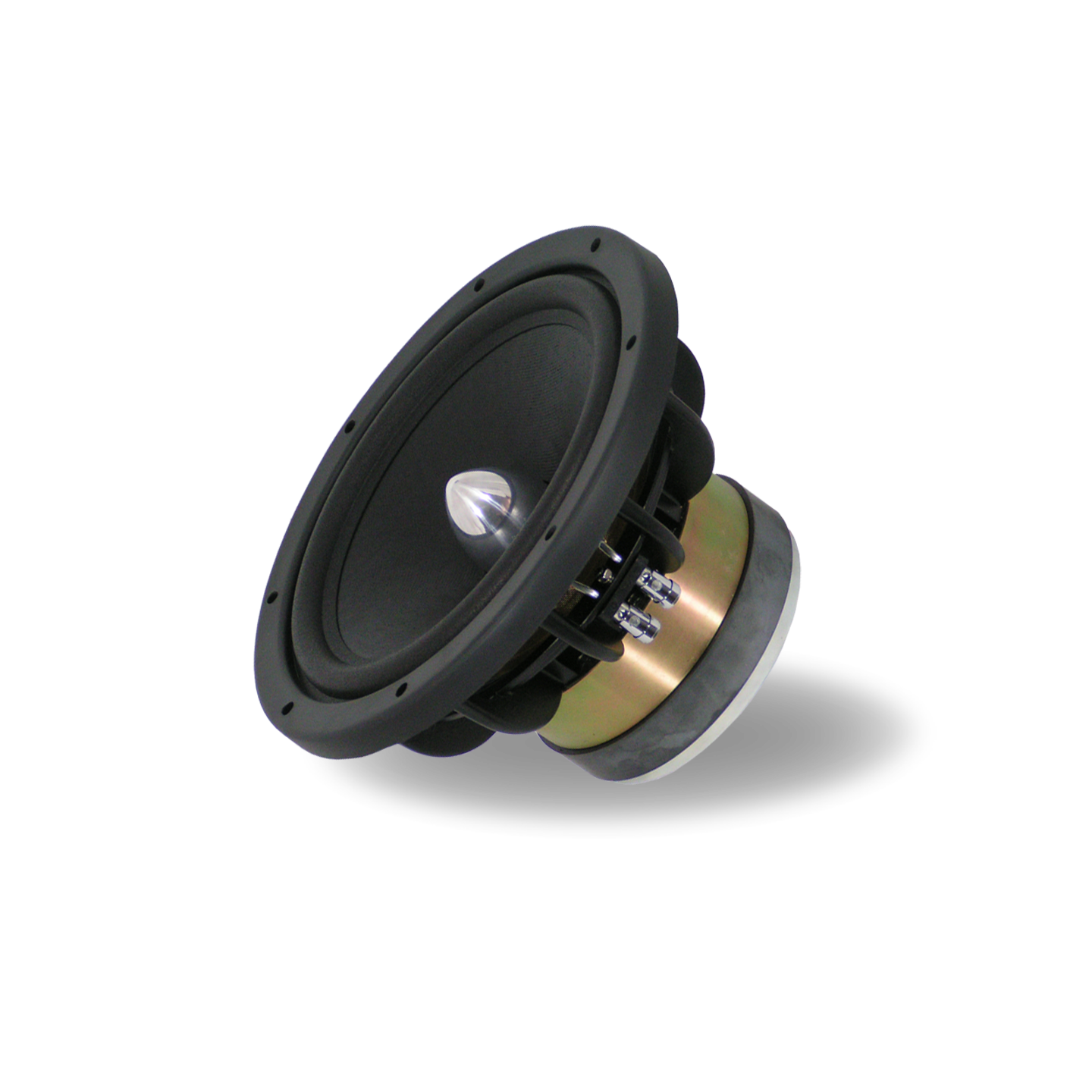
Very nice project the DIY ribbon and B&G midrange certainly do perform exceptionally well.
The choice of the AT drivers for the woofers is a little strange all things considered. They don't really bring anything special to the table except their price tag. Gornir has measured it here.
www.audioexcite.com AudioTechnology 10C772510KAP
And its performance is lacklustre to say the least.
The choice of the AT drivers for the woofers is a little strange all things considered. They don't really bring anything special to the table except their price tag. Gornir has measured it here.
www.audioexcite.com AudioTechnology 10C772510KAP
And its performance is lacklustre to say the least.
Very nice project the DIY ribbon and B&G midrange certainly do perform exceptionally well.
The choice of the AT drivers for the woofers is a little strange all things considered. They don't really bring anything special to the table except their price tag. Gornir has measured it here.
www.audioexcite.com AudioTechnology 10C772510KAP
And its performance is lacklustre to say the least.
Thank you
It still amazes me that it's possible to DIY a driver that performs so well.
The AT drivers were selected for their large excursion capability combined with low fs and low Mms. Gornir does use this driver in his Sequence Three – Grand Reference. To quote:
Troels Gravesen also has a lot of good things to say about this driver and I heard good reviews from others. When I have the chance to measure my system in an anechoic room the measurements will show how they perform in an open baffle. Subjectively it is a big improvement over the Orion, much more detail in the bass and lower mid.This loudspeaker is fast with very nice micro dynamics and they don’t need much power to bloom out. This is a speaker that can be listened to at low listening levels and still be enjoyable.
What would you suggest as a lower cost alternative 10" driver?
regards,
Gerrit
T
What would you suggest as a lower cost alternative 10" driver?
regards,
Gerrit
Peoples subjective opinions on how a driver sounds are completely pointless and irrelevant. The way the thing measures says everything you need to know. This is especially true when considering a driver that is going to be operating before its cone starts going through any kind of breakup and before it starts to beam.
The AT has decent xmax, almost all 10" drivers have a low fs and its mms is irrelevant. The end net sensitivity of the thing is what matters as a factor of motor strength vs moving mass.
The real issue with the AT is its motor linearity. Look at Gornir's measurement on AudioExcite.


Not only are their huge consistency issues (one drivers performance is significantly worse than the other) but all orders of distortion are poor. For a driver of this price (some 650 Euros) the 5th order should be at ~0.01% over its entire operating range. The 3rd harmonic should be at, or better than 0.1% and the 2nd harmonic below 1%, ideally mirroring the performance of the third harmonic, this is rare, but it can happen. As you can see the AT doesn't get anywhere near this level of performance, its motor and suspension are seriously underwhelming.
Drivers I would use over the AT.
Dayton RS270-8.
Peerless SLS 830668
SEAS Prestige L26RFX/P
SEAS Prestige CA26RFX
SEAS Excel W26FX-002
SEAS Excel W26FX-001
ScanSpeak Revelator 26W/8861T
ScanSpeak Revelator 26W/8867T
Acoustic Elegance Dipole Series Dipole10
Acoustic Elegance TD10S
Just to name a few. You've got ncores powering this so you've got more than enough power to push any of the drivers there into its mechanical limits, so a dB or two difference in sensitivity is a moot point.
The budget option would be the RS270 from Dayton. They may not be expensive but the motors on those drivers are exceptional. You need to really spend the pennies to get something better.
Next along the chain I would go with either of the 10" Excel drivers from SEAS. These manage to pip the Dayton both in terms of absolute linearity and power handling, so are an upgrade but at a rather large price.
The cost no object choice would be the Dipole driver from Acoustic Elegance. These have huge underhung motors with very thick top plates giving 12mm of one way xmax.
Really though I'd be very happy with the SEAS drivers although I'd be torn between the mag cone and its complete absence of cone edge/surround resonances and the Nextel cone for its slightly higher sensitivity. Although with ncores powering the things the sensitivity difference would hardly matter.
Keyser, thanks for the informative reply.
A ground-plane measurement on these no baffle (or worse yet, suspended driver) dipole speakers looks to be practically impossible... and how would you even begin to do horizontal off-axis measurements?
Putting the speaker and mic up on a stand looks like the better technique, even if it requires some engineering. The higher the better, but what is high enough for decent resolution for crossover design at, say, 300Hz? And what are your thoughts about mic distance?
can someone expand on the difficulties involved here? why can't you get good results outside in an open area? is it because there is a ground reflection?
Boundary reflections are the problem and ambient noise the other. To see the response impulse response gating must be set to such long time interval that eg. floor bounce comes visible and dominant. Alike indoors side walls, ceiling, front wall and back wall, furniture... And nearfiel measurements are useless for dipoles!
Indoor measurements are possible but unbelievably tricky. Outdoor measurements or anechoids are needed for learning to see those various indoor disturbances.
Right Juhazi, it looks like the only real option is to measure outside or in a very large warehouse space, and getting the speaker well off the ground. I'm interested in seeing just how people are handling the setup. I am considering a drywall hoist (I actually need this for installing drywall too!):
http://www.northerntool.com/images/product/2000x2000/233/23310_2000x2000.jpg
http://www.northerntool.com/images/product/400x400/233/23310_2_400x400.jpg
It can lift 150lb. supposedly. I'd need to add a turntable on top of the platform for off-axis, and a boom to hold the mic in place. Wrap the struts with foam. The nice thing is this rig can be cranked up 11ft. off the ground! What could go wrong?
I measured my AINOgradient out on my backyard which has grass. Put the speaker on a 1m high kitchen ladder + turntable and the mic 2m away. Building walls were 5-6m away but gave very loud echos.
This session however helped a lot to see the dipole loss of mids without boundary reflections. Still ground reflection came visible with long gating. I did some ground plane measurements too, but it can't be used for crossover tuning (delay setting) unless you can put the mic 3-4m away.
My system is very difficult to uninstall and move, I haven't put it outdoors since.
I use a camera tripod as mic stand.
- Status
- This old topic is closed. If you want to reopen this topic, contact a moderator using the "Report Post" button.
- Home
- Loudspeakers
- Multi-Way
- The Totem of Tone, an active 3-way dipole and active subwoofer