When measuring drivers with Speaker Workshop that have a high Qms, I often get impedance spikes that are VERY high, like 100 ohms. Thinking it was because my rig was not calibrated correctly I went through the calibration steps very carefully and even calibrated sound card impedance, etc. No change resulted.
I know the measurements are wrong because if I measure a 50 ohm resistor after calibrating with 5 and 15 ohm resistors, I get 75 ohms or some such nonsense. If I calibrate with higher resistances, it can make the lower resistance readings wrong. Calibrating with three or more resistors never converges to reasonable readings in SW (for me anyway).
I have tried several sound cards and also used Soundeasy, which gave similar errors. Throwing this out there as I have come across this a couple times and haven't yet isolated a cause. I haven't given it much thought, and wondered if someone else here has found a solution for this ? What is the source, can anyone hazard a guess?
I use speaker workshop but not for measurement, in fact I've never tried. Something about it. Besides, the microsoft sound interface has changed and other older measurement programs have been flaky.
What I do is take the impedance plots in HolmImpulse, then export them as a text file. When you get this set up the files go straight across.
What I do is take the impedance plots in HolmImpulse, then export them as a text file. When you get this set up the files go straight across.
The voltage available from a soundcard is so small and weak that it is a poor source for speaker measurements without a power amp inbetween. A lot of people seem to make this mistake!
Also, 1k for the pseudo current source resistor is a source of error when dealing with speakers that have a high Zmax. I try not to use less than 2.2k.
Also, 1k for the pseudo current source resistor is a source of error when dealing with speakers that have a high Zmax. I try not to use less than 2.2k.
Last edited:
as you are getting the wrong results when testing a fixed resistor, you need to go back and check your jig/wiring, and calibrate from the start ( loop clip levels etc).
as has been said already, you should also be using a power amp between the soundcard and DUT.
once correctly setup, you should be able to measure a fixed resistor with good accuracy and that the trace shown should be flat and clean, no noise spikes.
as has been said already, you should also be using a power amp between the soundcard and DUT.
once correctly setup, you should be able to measure a fixed resistor with good accuracy and that the trace shown should be flat and clean, no noise spikes.
I'm fairly sure I tried an amp (unity gain) already, as I do all acoustic testing with an amp. The computer concerned is a laptop with XP, so I don't think windows sound issues are the problem. The laptop has a fairly strong amp inside, so it is not quite like a bare soundcard. I'll give the amp another try and report back this weekend. Thanks!
Was considering making a minimalist Pete Millet test box before posting my question") Is there a good way to go from a decent lithium battery pack to the +/-12-15 V that an opamp circuit and small amp requires? Looking to make it portable and battery powered.
Is there a good way to go from a decent lithium battery pack to the +/-12-15 V that an opamp circuit and small amp requires? Looking to make it portable and battery powered.
Was considering making a minimalist Pete Millet test box before posting my question
Is there a good way to go from a decent lithium battery pack to the +/-12-15 V that an opamp circuit and small amp requires? Looking to make it portable and battery powered.
Last edited:
What value resistor are you using in your speaker workshop jig as the load resistor? I know the original walin jig specified an 8 ohm resistor, but some of the other software I've seen says to use 100 ohms or a few K.
If your using between 8 and 10 ohms for the load resistor you could try putting in a bigger value. I'm pretty sure when I measured higher value resistors the accuracy was not good.
I stopped using speakerworkshop for doing my impedance measurements and use REW now. I found that certain woofers gave me resonant frequencies that were way off with speakerworkshop, but REW is spot on. I don't know why because it is only with some woofers not all.
I do my impedance measurements straight off the sound card output and haven't had issues, but I suspect my ancient audigy II ZS and my current focusrite 2i2 have pretty decent outputs that don't load down with the low impedance of the drivers being tested.
Tony.
I know the measurements are wrong because if I measure a 50 ohm resistor after calibrating with 5 and 15 ohm resistors, I get 75 ohms or some such nonsense. If I calibrate with higher resistances, it can make the lower resistance readings wrong. Calibrating with three or more resistors never converges to reasonable readings in SW (for me anyway).
You possibly have your input channels swapped.
I stopped using speakerworkshop for doing my impedance measurements and use REW now. I found that certain woofers gave me resonant frequencies that were way off with speakerworkshop, but REW is spot on.
With SW and SE, you must select the right (read lower) sampling rate, else the low frequency resolution will be poor.
Hi Shaun, I do somewhat remember that, I think I used to use an odd sampling rate like 16Khz (which my new soundcard can't do, it's lowest is 44.1Khz)
When I said load resistor above I was talking about the resistor in series with the DUT, as per SY's comment above I really should at some point try modifying my jig to use a bigger resistor and compare the results...
Tony.
When I said load resistor above I was talking about the resistor in series with the DUT, as per SY's comment above
I really should at some point try modifying my jig to use a bigger resistor and compare the results... Tony.
OK, as I woke up this morning it became intuitively obvious that high output impedance will cause the sensed voltage to depend on loudspeaker impedance, giving higher voltages for higher impedances, causing the sensed impedance to increase. Now to figure out the circuit and see if a higher test resistor will impact accuracy, and how little output impedance is needed with a given Test resistor size to minimally effect accuracy.
Looks like intuition was wrong?
Neglecting sound card input impedance, the voltage at the right channel is just the voltage at the left channel divided by (1+Rt/Rl) where Rt is test resistor and Rl is loudspeaker. Output impedance reduces both left and right channel voltages proportionately. I'll have to dig into this more...
Neglecting sound card input impedance, the voltage at the right channel is just the voltage at the left channel divided by (1+Rt/Rl) where Rt is test resistor and Rl is loudspeaker. Output impedance reduces both left and right channel voltages proportionately. I'll have to dig into this more...
You'll only be using one output channel wont you? Conventional measurement styles calling for a large enough series resistance to approximate a current source tend to be insensitive to this anyway.
Output impedance can be found as the value of load that halves the amp output compared with no load.
Output impedance can be found as the value of load that halves the amp output compared with no load.
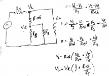
Here's the math - in the diagram, Vg is generator resistance Rref is test resistor, Rs is speaker, VL and RL are the voltage and impedance of left soundcard input, Vr and Rr are for right. I ignored Rl and Rr for simplicity in this pic, but I did the analysis and it doesn't change much if you include it.
Attachments
Ron, starting to lose sight of what the question is. You are right in that a larger value of resistor gives the sensed signal accuracy in absolute terms.. the series resistor can be small and still be accurate if it is accounted for, which is typically easiest when your program does this for you, such as Limp (with Arta).
However some find getting the measured signal out of the noise is the pressing issue. This is where the power amp helps, and the benefit comes with the voltage gain. Source impedance, while important doesn't need to be as low as our speaker amps, even though that's what often gets used.
However some find getting the measured signal out of the noise is the pressing issue. This is where the power amp helps, and the benefit comes with the voltage gain. Source impedance, while important doesn't need to be as low as our speaker amps, even though that's what often gets used.
- Status
- This old topic is closed. If you want to reopen this topic, contact a moderator using the "Report Post" button.
- Home
- Loudspeakers
- Multi-Way
- Sound card impedance measurements