Any impressions?Re: your chosen CAD software, I will be attending a free CREO training workshop the next couple of days. Will be good to see how it compares to Solidworks.
I'm a SolidWorks fan. I took a ProE course (now Creo) and I hated it.
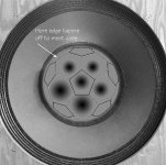
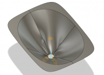
Hey Bill. A few years ago I decided to do that, to replace missing horns on a pair of Altec/Urei 15" coax. The idea was to do a mix of pentagon and hexagon, like a soccer ball. It's a shape that allows tight packing. The image below was what I started with. It was all rendered in 3D and STL but never printed. I've searched and searched, but can not find the files.I think it would be pretty straightforward to 3D print a waveguide which is divided into many smaller horn-lets, like a multi-cell but with the openings at the end no more than about 6mm square (to avoid combing).
 I also planed to make a horizontal horn of similar design, 3 rows high and 5 or six wide.
The openings would need to be small, and that could be a problem. I've been doing a bit of 3D printing lately, and getting fine detail isn't easy. I job the printing out to 3D hubs and there are several printers in my area. There is a big difference in quality between printers and pint operators. 2mm opening might be possible with some of the printers I've worked with. Small would be difficult. I'm sure some of the guys here can shine more light on that.I imagine it might be lossy because of all the surface area the overall wave would have to get past (and the openings of the tubes would have to be very small at the throat end).
FWIW, if your prints are ABS,you can smooth them with an acetone vapor bath. There is plenty of info on the webs and on YouTube.
Attachments
From what we learned in the Paraline threads, the apertures would need to be between 0.425 - 1.7cm in diameter. This is because 20khz is 1.7cm long. Basically you want to make the apertures small enough that the wavefront won't form.
The most difficult part is that the device would need to go INTO the compression driver throat. This is to prevent waves from forming in the throat of the compression driver.
Where this gets REALLY fun is that you could use this technique to make waveguides with wide coverage and high compression. Here's what I mean by that:
In a conventional waveguide, you have to trade coverage for efficiency. For instance, Danley sells a Synergy horn with a twenty five degree coverage angle and very high output. The reason that it's output is higher than the SH50 is simple: the SH50 is radiating into an angle that's twice as wide.
With Bill's device you could achieve similar results by 'filling in' half of the waveguide. So you'd have a waveguide with wide coverage and high efficiency.
On second thought, this ALSO gets tricky. Because all of those cells will behave like independent sources. Due to that, you'll get comb filtering from cell-to-cell.
Due to that last point, the depth of the device will be very limited. To prevent comb filtering, the gap between cells would have to be very small.
BTW, this would be super easy to render. 123D is really handy with these types of geometric arrays.
So, Patrick, can we be expecting a printed horn from you imminently, based on this scheme
I was wondering whether the issue of needing small mouth cell size (to avoid comb filtering) and the reduction from that to super-tiny throat cell size (because of horn mouth/throat area ratio) could be mitigated by 'breaking it up' -- start with fewer 'straws' at the the throat, then at (preferably irregular) distances from the throat subdivide each of those into multiple straws. Kind of branching out as it goes in both cross-sectional area and number of straws (cells), so that cell size stays below a quarter wavelength but the initial cell size is still manageable (and the plastic/air ratio at the throat doesn't get too high). Wish I could figure a way to sketch that, hope you can see what I'm thinking.
edit: hexagons and pentagons would both break up nicely into triangles...
edit2: I seem to be unable to type "ratio" without adding an 'n' onto the word!
Last edited:
Yeah, that lost file is driving me crazy. The work was done by someone else before I learned how to do the 3D files. It was going to look something like the image below. Perfect for 3D printing.
Agree about the smoothness, rough is probably better for the horn. Just a FYI on getting smooth if needed.
Agree about the smoothness, rough is probably better for the horn. Just a FYI on getting smooth if needed.
Attachments
Any impressions?
I'm a SolidWorks fan. I took a ProE course (now Creo) and I hated it.
My initial impression is CREO's freestyle/freeform surfacing tools offer increased design flexibility and improved workflow when developing 3d models over Solidworks.
My initial impression is CREO's freestyle/freeform surfacing tools offer increased design flexibility and improved workflow when developing 3d models over Solidworks.
This is true, sketching is also slightly faster because of the visual relations feedback on the tool hints.
Curvature continuous curves are a joy in Creo and would be perfect for this project, like this tonearm.
An externally hosted image should be here but it was not working when we last tested it.
I still prefer SW and do most of my tinkering in it.
I liked Creo free version - just old style enough to have actual text and examples in the help, maybe cumbersome but easy to grok ribbon menus
Fusion 360 however is likely better for freeform design - and full functionality is free for hobby use, but without Creo's free version limits
but the developers, most of the community seem to think hundreds of few minute videos constiutes documentaiton
Fusion 360 however is likely better for freeform design - and full functionality is free for hobby use, but without Creo's free version limits
but the developers, most of the community seem to think hundreds of few minute videos constiutes documentaiton
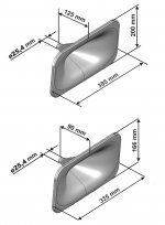
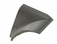
xrk was asking for a STL for 1" compression drivers. Here's a few 90x60 horns that have the following parameters:
W_total: 210 mm
H_total: 130 mm
D_total: 95 mm
R_throat: 12.7 mm
R_vert: 20 mm (vertical roundover at mouth)
R_hor: 50 mm (horisontal roundover at mouth)
Alpha_vert: 30 degrees (vertical coverage = 60 degrees)
Alpha_hor: 45 degrees (vertical coverage = 90 degrees)
N: 1.5 (superellipse)
The geometry has been simplified according to suggestions from andy19191. The mounting holes are 76 mm apart and 6.5 mm diameter (should suit M6). Calculated printing time for 3 shells and 30 % fill is 5.5 hours with my printer.
The throat angle differs according to file name.
7 deg should suit BMS 4550 and B&C DE250.
12 deg should suit CDX1-1445, CDX1-1440, BMS 4552, B&C DE12.
I have not tried printing any of these. I recommend low printing speed for the first layers as the overhang angle is large initially but will quickly decrease.
I can easily make other similar waveguides (other dimensions or angles), just ask me if you feel like printing one
Here is what the geometry looks like:


/Anton
Hello Onni, I was trying to get hold of SEOS-12 & SEOS-15 waveguides from diysg but they have been out of stock for months and months and there are no local Autotech re-sellers for for these horns in Australia (I am very late to the party). Perhaps you could modify your example to something like those horns so i could try and 3D print those instead (I am guessing the SEOS ones have a much larger horizontal roundover in the mouth.
I have a couple of DE250s waiting without a mate for a few months and has driven me to look at 3D printing route.
Attachments
you can generate a OS surface by rotating a section of a hyperbola about a axis
may have to enter the hyperbola as a spline thru calculated points
I have used literal conic section construction - rotate triangle to get a cone, slice the cone with a plane offset but parallel to the axis, project the cut face/edge hyperbola to a construction plane and then rotate about a new axis for the OS waveguide shape
I tried this method and it turned out to be much, much easier than previous attempts I had made. Tracing a spline to an image exported from someone's Excel spreadsheet with oblate spheroid equations in it can sort of work. This is better though.
Attached is a Fusion 360 file with a history timeline showing how to do it. I also created three different offset planes in order to see how the different generated hyperbolas would compare. It turns out that as you get further from the midplane with your cutting plane, the generated hyperbola has a softer bend to it. I guess it would probably take some ABEC or COMSOL modeling to figure out which of those hyperbolas works out to be optimal for a given throat exit angle and frequency range.
Oh, and on that note, I'll go ahead and document something I found here while working with an EV ND6 driver (probably equivalent to the often talked about DH1A). If you trace the EV ADH-6 1.4" to 2" throat adapter shown on the EV ND6 data sheet, it comes out to about a 10.6 degree exit angle. I haven't seen that info written down anywhere else.
Attachments
An attempt at a 1.5 inch throat imitation of the QSC HPR152i/PRV WG35-25-B
Is there a more active thread I should be posting about 3D printed waveguides in? This one's got good information about using the oblate spheroid curve, so I'm updating here unless someone tells me not to...
Attached is a .zip with the .stl and .f3d (Fusion 360 file including history) for the quarter-horn I've generated mimicking this guy: PRV Audio WG35-25-B 1" 90 x 60 ABS Waveguide 2-Bolt. I have a couple of drivers I'd like to try with it.
The geometry on the back side is kind of a mess since I haven't figured out a good workflow yet for creating an object of constant thickness. Maybe that's my next step... anyway...
The specific model of the horn attached right now doesn't have a flange attached yet but has been cut off for a compression driver with a 10 degree exit angle (a few steps earlier in the history, the oblate spheroid profile was generated from a symmetrical hyperbola giving a 0 degree throat angle, so I drew some tangent lines and made a cutting plane about half an inch from the base to give a 10 degree throat that's about 1mm/0.04 inches larger than the 1.4 inch throat I started with).
About half way along the depth of the horn, the profile changes. At the throat, it's a radially symmetrical oblate spheroid profile. At the half way point that surface is lofted to the 14"x10" mouth of the horn, with splines matching the angle of the OS curve along the vertical and horizontal border.
I went with this approach because a previous attempt in Fusion 360 to loft along rails for the entire oblate spheroid curve for a horn with a superellipse or rectangular mouth gave these weird dents on the diagonals that looked oddly like the JBL M2 waveguide. This made me wonder if a workflow like this may have accidentally led someone down that path. If I ever figure out what I'm doing wrong that creates those, maybe I'll redo this with a workflow more like what's shown in Creo in the rest of the thread. Until then, the radial-to-rectangular loft seems to look pretty nice. Maybe I'll play around in ABEC if I can figure that out. If you're reading this and you know how to use it though, could you give it a try?
Attachments
Last edited:
Ok time to bring this topic up since interesting development in the ATH thread, large hobby printer friendly waveguides
https://www.diyaudio.com/forums/multi-way/338806-acoustic-horn-design-easy-ath4-761.html#post6742622
What printer to get as first one for misc audio projects? I think reliability is more important factor than print quality, i've got no time to waste fighting with silly issues and can outsource if quality is required. Or does quality and reliability go hand in hand?
Found out Creality has a model CR-200B with cabinet to keep heat inside which should increase success rate? If print area about 20cm * 20cm * 20cm is enough, what would you buy? ease of use, low noise, reliability, preferably cheaper than expensive. Thanks
Last edited:
I am no expert in 3D printing but I recently bought a Sovol SV01 when it was on sale for $249 USD. The only thing I needed to do was straighten the X gantry by undoing a couple of bolts. I bought the BLTouch option which was awkward to install but not difficult and that makes getting a good first layer and good prints easy.What printer to get as first one for misc audio projects? I think reliability is more important factor than print quality, i've got no time to waste fighting with silly issues and can outsource if quality is required. Or does quality and reliability go hand in hand?
The prints are really good in PLA and seem to be above average for a printer with absolutely no tweaking or benchmarking done.
I have not regretted buying it. There is a soft foil enclosure that can be bought if you are thinking of using filaments that need it. I made a makeshift one out of foam gym mats to print ABS and it worked to keep the temperature up and draughts out. Trying to get the bed adhesion right with ABS is a pain. For now I'm sticking to PLA for ease of use it seems to be almost immune to whatever the environment is.
- Home
- Loudspeakers
- Multi-Way
- 3D-printing