those input conjugate matching networks will never effect the sound for any good voltage amp with reasonable damping factor. <full stop> IMO they are for making pretty impedance charts on a computer. or perhaps vacuum tube amps with low feedback and not enough power to due any justice to these low eff. drivers.
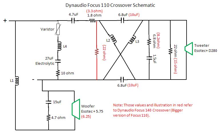
1.In the lattice filter, the difference between
6.8uF and 10uF of the Focus 140 means ...?
The difference is the difference between Focus 110 XO
frequency(1,6 kHz) and Focus 140 (2,4 kHz). The filter
changes tweeter's FR and Phase .
2. I believe the varistor is the fail safe for the amp
consider irregularity of electrolyte cap, is it correct?
It is not a varistor. You showed in pdf it is a PTC resettable
fuse R110, means it holds current of 1,1A. See datasheet.
It is not connected in series with RLC. You got it wrong
in the schematic. It is in series with tweeter. Its purpose is
to protect the load (tweeter) in case current reaches
critical value. Then it acts as a higher value resistor making
tweeter output attenuated.
3.Consider the temperament of the electrolyte, what
can we expect of the sound when dissipation factor is
high or irregular?
RLC circuit has only one purpose. To flatten system impedance.
The manufacturer has installed one for the users having amplifiers
sensitive to huge impedance fluctuations.
4.Can we perceive the midrange may have some harshness
because of non linear behavior of the electrolyte?
No harshness can originate from this cap.
5.Correct me if I am wrong: Circuit of varistor+ L4 + 27uF
+ 10 ohm is a band pass filter. It is to deal with the resonance
frequency of the tweeter. From what I can find, fs=1300Hz.
Read the answer to 3rd question.
6.From the various sources in the internet over the Focus 110
Frequency Response graph, you can see a surge of around 5dB
from 5kHz to 7kHz. This region should very much exaggerate
the sibilance in a vocal track. But the off axis measurement of
15 to 30 degree has somehow flatten this peak.
If there is such peak, it can't do what you believe it can.
Dynaudio speakers do not suffer from this.
7.In Asian country majority of our houses are of concrete and tile,
which make this quite audible. So I need to know the sibilance has
something to do with band pass filter, since electrolyte cap is a bit
non-linear around the audible range of frequency?
Read the answer to 3rd and 6th question.
8. I am sorry I post these questions as I dont have the luxury of
measurement toys or other tools to verify it. Neither that I know
how to use it correctly if I have oneChanging components in
and out of the speakers to find out what are and what arent will
most likely wear off the screw holes or causing more handling
damage.
This is not about luxury. It's about you not willing to study.
Simulation software is free. Computer you already have or not?
It makes no sense to waste time arguing what would happen to what
frequency without using modern aids like simulation programs.
9.So I would like to get you guys which have great experience to
make some eudcated guess into how it may sound when something
is changed.
Read the answer to the 8th question.
Hi Lojzek,
Thanks for the honest response and criticism.
Question 1, FR you refer to is the Frequency response?
Question 2, of the resettable fuse, I have checked many times over. It is not in series with the tweeter.
Question 3, System impedance. The system you refer to is the loudspeaker?
Hi System 7 and Tattoo,
Appreciate your feedback on the questions in Page 2 of this thread. Thanks.
1. yes
2. I can't say it makes sense to put it in series with RLC
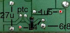
Could you make a sharp snapshot of the circuitboard from
the side where traces are? I know I have seen these fuses
in series with tweeter.
3.Yes, this is the impedance of the total and completed
loudspeaker.
2. I can't say it makes sense to put it in series with RLC
Could you make a sharp snapshot of the circuitboard from
the side where traces are? I know I have seen these fuses
in series with tweeter.
3.Yes, this is the impedance of the total and completed
loudspeaker.
Lojzek,
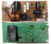
Attached the layout. The PCB layout is inverted for easy comparison.
The cable tie that hold the L4 only has the direct link with the resettable fuse. There is no continuity between L4 and R3.
Attached is also the latest data of the possible tweeter used. I know about the old website of all the DIY version of the dynaudio and driver. But this is clearer. See the resonance peak?
I will share later of the graph on the 5kHz to 7kHz peak.
Attachments
Last edited:
A resettable fuse makes some sense, assuming the
schematic is correct. It will cutoff the impedance
correction, increasing the impedance of the speaker,
reducing current, lowering movement of the tweeter.
It will act as a compressor/limiter.
If the schematic is correct, and I doubt it is, it does not
make a difference to tweeter dissipation whether fuse
trips or not, because it does nothing to tweeter output.
Tweeter receives the same voltage and the resistance in
series with tweeter doesn't change.
It is now clear to me that the fuse is in series with RLC.
Assuming this is a resettable fuse, what it does, it does
not protect the tweeter at all. At certain voltage, it protects
the amplifier by decreasing current flowing through the
fuse+RLC branch. The voltage and current flowing through
the tweeter does not change, no matter what fuse is doing,
according to your schematic.
The fuse is not to deal with the electrolyte when it DF increases
or failure during old age, thus protecting the tweeter?
The fuse reacts to voltage coming from amplifier. Once it reaches
critical level, the fuse trips and decreases current in the RLC.
Whatever happens to electrolytic capacitor, it does not change
tweeter performance. Neither current, nor voltage at tweeter
changes.
So, according to your schematic, tweeter has no protection whatsoever.
The only protection it gets, comes from user, who is in charge of volume
control.
It is now clear to me that the fuse is in series with RLC.
Assuming this is a resettable fuse, what it does, it does
not protect the tweeter at all. At certain voltage, it protects
the amplifier by decreasing current flowing through the
fuse+RLC branch. The voltage and current flowing through
the tweeter does not change, no matter what fuse is doing,
according to your schematic.
Your right.
I just did a bit of simming of this circuit, and as expected, if you increase the 4.7uF to 6.8uF, shunt the tweeter circuit with a 0.2mH coil and flip the tweeter polaruty, and strip out the lattice circuit altogether, you end up in much the same place!
A standard sort of 12dB/octave second order tweeter that might actually sound better. Many ways to skin a cat.
- Home
- Loudspeakers
- Multi-Way
- Dynaudio Focus 110 and 140 Crossover Comparison Details