Hi guys,
Been using my speakers for a while - PA/party use. They're a pair of old EV 15" Deltamax cabinets - Beyma 15P1200Nd and a big horn with an EV DH1a compression driver. There's often feedback problems in the 200Hz range, and, knocking on the sides of the cabinet, that would appear to be where the panels resonate. I suspect the panels are throwing lots of lower-midrange energy sideways.
So, I'd like to add some bracing.
The cabinets are trapezoidal, ~750mm tall, ~250-450mm wide (back and front), and ~300mm deep. The compression driver takes up a significant chunk of the top half, and touches the back panel (part of which is removable).
The 15" drivers aren't that deep, but there are side-handles to contend with - see below.

I don't want to add masses of bracing because, at the end of the day, I've gotta hoik these on to stands. So, keeping it simple, what would you do?
I'm thinking a couple of bits of 12mm ply glued for an x-shaped cross-section joining the two side panels would give good results - that'd give some support against lots of different bending modes of the panels.
Cheers
Chris
Been using my speakers for a while - PA/party use. They're a pair of old EV 15" Deltamax cabinets - Beyma 15P1200Nd and a big horn with an EV DH1a compression driver. There's often feedback problems in the 200Hz range, and, knocking on the sides of the cabinet, that would appear to be where the panels resonate. I suspect the panels are throwing lots of lower-midrange energy sideways.
So, I'd like to add some bracing.
The cabinets are trapezoidal, ~750mm tall, ~250-450mm wide (back and front), and ~300mm deep. The compression driver takes up a significant chunk of the top half, and touches the back panel (part of which is removable).
The 15" drivers aren't that deep, but there are side-handles to contend with - see below.
I don't want to add masses of bracing because, at the end of the day, I've gotta hoik these on to stands. So, keeping it simple, what would you do?
I'm thinking a couple of bits of 12mm ply glued for an x-shaped cross-section joining the two side panels would give good results - that'd give some support against lots of different bending modes of the panels.
Cheers
Chris
Patent US7270215 - Loudspeaker enclosure with damping material laminated within internal ... - Google Patents
Maybe somnething like Fig. 7 , but oriented to srut the driver's magnet against the "smaller" rear baffle or the joints of the rear baffle if the cabinet is sufficiently rigid there.
That strut should be able to take "push" an "pull" forces and have inherent damping.
Two (rigid) cardboard (or aluminum?) cylinders sticked together and the inside gap inbetween them filled with some dampening glue could be a "model" for that strut.
Outer cylinder glued intimately to the driver's magnet, the inner one glued intimately to the rear baffle or vice versa. Of course a kind of "adapter" will be needed at both sides for glueing.
Both cylinders only have contact via dampening glue in their common gap. Gap may also be filled by some kind of viscoelastic material, to save glue.
If area of adapters is large enough, glueing (magnet, rear baffle) may even be using double sided adhesive tape (e.g. acrylate) of sufficient thickness and quality.
Just thinking ... no guarantee")
Maybe somnething like Fig. 7 , but oriented to srut the driver's magnet against the "smaller" rear baffle or the joints of the rear baffle if the cabinet is sufficiently rigid there.
That strut should be able to take "push" an "pull" forces and have inherent damping.
Two (rigid) cardboard (or aluminum?) cylinders sticked together and the inside gap inbetween them filled with some dampening glue could be a "model" for that strut.
Outer cylinder glued intimately to the driver's magnet, the inner one glued intimately to the rear baffle or vice versa. Of course a kind of "adapter" will be needed at both sides for glueing.
Both cylinders only have contact via dampening glue in their common gap. Gap may also be filled by some kind of viscoelastic material, to save glue.
If area of adapters is large enough, glueing (magnet, rear baffle) may even be using double sided adhesive tape (e.g. acrylate) of sufficient thickness and quality.
Just thinking ... no guarantee
Last edited:
I think I could sneak the bracing in between the horn and handles, or even butt the bracing against the handles if necessary.
Looking at the side of the cabinet, a brace that looks like x (not +) along its length seems to me to support a lot of material with fairly minimal work, except for getting the angles right.
Oliver, I like the cylinder idea, though I'm not so keen on putting anything against the driver's magnet. There are lots of vents on the back of the magnet, and these drivers see some power - I've nudged into the limiters on a NU6000DSP (~1.2kW/ch) for hours at a time, so I'm willing to bet the drivers get warm.
Another option that I'd consider less effective would be some triangles, joining adjacent panels. While individually less effective, if they let me brace areas that wouldn't normally have any support, that can't hurt, right?
Would there be any interest in measurements of this project?
I was considering getting a cheap acoustic guitar pickup and taking frequency response measurements of the cabinet walls with REW.
Cheers
Chris
I did not have much luck with guitar pickups for this. Mainly because my sound card just didn't play well with the pickup.
Interested to see the results, if you can get them, Don't see much published on this.
Not a problem, I've got a mixing desk - can have as much gain as I like. I need to make sure the EQs don't do anything to the signal, though - there's no hard bypass.
PKNJ, do you mean a single dowel, or several?
I think a single one would only damp out a few vibrational modes of the panel (picture standing waves) depending on its position, but a few of them would get a lot more. Very minimal work, too...
To the internet!
Cheers, all
Chris
Hi chris661,
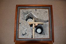
I use either a broom handle or better still, a shovel handle which are about 1" to 1 1/4" diameter. I get them from my local hardware/gardening store, but you may be able to get some from B&Q. Attached is what I did on a sub, but I've also used them very effectively on my floor standing main speakers. Attached is a pic of the sub.
Peter
Attachments
Alrighty then.
I've got some photos of the cabinets, below, and I've managed to get some measurements by unscrewing one of the screws in the handles a bit, and then clamping the pickup to the screw.
Looking up into the cabinet:

Through the bass driver cutout:

It looks like there's a cursory attempt at bracing in there, but this also forms the bottom shelf of the two slot ports.
Looking into the access panel:

Clamping to the handle:

I got lots of very ugly-looking graphs out. Usefully, it looks like one of the biggest feedback problems (191Hz) is definitely a panel resonance. There's also a lot of stuff going on up to about 600Hz.
How would you guys like the data to be presented?
I've about 10 graphs, each one taken at a different point on the handle, or summations of two pickups in different places.
So far, I'm thinking of 2 cross-braces towards the bottom end, and one underneath the horn but well above the bass driver.
Chris
You could always apply some thick felt on the larger outside panels...with a cut-out for the handles. If you have a teenager come up to you & asks what the felt is for...Just tell them it's there to keep your valuable loudspeaker system warm.
______________________________________________________Rick.........
______________________________________________________Rick.........
Interesting that the resonances are up so high. That may be hard to deal with by bracing. But it's worth a try!
Be sure you know the exact location of your pickup, for repeatability. I still think big round dowel (what is often called Closet Pole) is the way to go. Do you need one, or three? Hard to say. But you are armed with the methods to find out.
On my big Altec boxes I had to brace, thicken the walls and use bitumen mixed with sand on some parts. A royal pain, but it worked wonders.
The pickup locations are just the screws holding the handles in - plenty of repeatability there
I have two of these cabinets, so I'm going to get some dowel and take measurements after adding each one, with comparison to the original.
I'm also wondering if I could add a front-to-back brace, for additional baffle support. I'd probably just extend the half-a-shelf back with a single dowel and call it good - anything is better than nothing at all.
Anyway, without further ado, here's some spectacularly nasty looking graphs. The datapoints are offset against each other for clarity, and I'll talk through each one in a moment.
First, though - the handle has 10 screws, 3 along the short edges, 4 along the long ones.
Top middle = top of the handle, middle screw
Bottom front = bottom of handle, nearest the baffle.
First up, bottom of handle, blue is front, pink is back.
Front of handle, blue is bottom, green is top.
Lastly, middle of handle, pink is top, and the icky green-blue is bottom.
So, things to note:
- the 200Hz is pretty well everywhere, as is the 430Hz.
- the 270Hz peak only occurs in some measurements, so only careful placement will get shut of that.
- the pink/blue trace looks like its gonna have another peak around 800Hz.
- its amazing these sound anything like as good as they do.
- I suspect the 200Hz resonance will disappear if I brace pretty well anywhere, since it appears in all measurements.
Next steps:
- draw up a map of where bracing would be most effective, noting the 270Hz in particular.
- get hold of some dowel, min 1" diameter, and add it to the cabinets according to the previous step.
- lots more measurements.
- line the cabinets with some felt, mostly to kill reflections coming back through the LF cone.
Pano, why do you find the resonant frequencies surprising?
The fundamental is 200Hz, so it makes sense to have some harmonics thereof, no?
Chris
PS - I've just thought that this could be done to any speaker cabinet, by putting screws in on the inside, and sweeping. The contact pickup would only collect signal from the panel, so it'd be the same as measuring the outside, but without putting screws through your shiny new veneer.
I have two of these cabinets, so I'm going to get some dowel and take measurements after adding each one, with comparison to the original.
I'm also wondering if I could add a front-to-back brace, for additional baffle support. I'd probably just extend the half-a-shelf back with a single dowel and call it good - anything is better than nothing at all.
Anyway, without further ado, here's some spectacularly nasty looking graphs. The datapoints are offset against each other for clarity, and I'll talk through each one in a moment.
First, though - the handle has 10 screws, 3 along the short edges, 4 along the long ones.
Top middle = top of the handle, middle screw
Bottom front = bottom of handle, nearest the baffle.
First up, bottom of handle, blue is front, pink is back.
An externally hosted image should be here but it was not working when we last tested it.
Front of handle, blue is bottom, green is top.
An externally hosted image should be here but it was not working when we last tested it.
Lastly, middle of handle, pink is top, and the icky green-blue is bottom.
An externally hosted image should be here but it was not working when we last tested it.
So, things to note:
- the 200Hz is pretty well everywhere, as is the 430Hz.
- the 270Hz peak only occurs in some measurements, so only careful placement will get shut of that.
- the pink/blue trace looks like its gonna have another peak around 800Hz.
- its amazing these sound anything like as good as they do.
- I suspect the 200Hz resonance will disappear if I brace pretty well anywhere, since it appears in all measurements.
Next steps:
- draw up a map of where bracing would be most effective, noting the 270Hz in particular.
- get hold of some dowel, min 1" diameter, and add it to the cabinets according to the previous step.
- lots more measurements.
- line the cabinets with some felt, mostly to kill reflections coming back through the LF cone.
Pano, why do you find the resonant frequencies surprising?
The fundamental is 200Hz, so it makes sense to have some harmonics thereof, no?
Chris
PS - I've just thought that this could be done to any speaker cabinet, by putting screws in on the inside, and sweeping. The contact pickup would only collect signal from the panel, so it'd be the same as measuring the outside, but without putting screws through your shiny new veneer.
Last edited:
I think I was surprised by the amplitude and quantity. Of course your pickup frequency response may be skewing that view.Pano, why do you find the resonant frequencies surprising?
The fundamental is 200Hz, so it makes sense to have some harmonics thereof, no?
Looking forward to seeing what comes of this.
Yep, those peaks look 20dB up on the "nominal" range.
Its a piezo pickup feeding into the microphone input of a DJ mixing desk. I'd potentially expect a 6dB/octave decrease in signal as frequency drops.
Looking at the graphs, I'm particularly surprised by the first one: at low frequencies, there's a large difference in the pickup response, despite a fairly small distance offset, and the very large wavelengths involved.
A friend of mine has access to some software that can model these things, so I've sent off the cabinet dimensions to see if we can get simulation matching experimental results, and then bracing can be optimised by the software instead of trial and error.
Chris
- Status
- This old topic is closed. If you want to reopen this topic, contact a moderator using the "Report Post" button.
- Home
- Loudspeakers
- Multi-Way
- How to brace MY speaker cabinet?