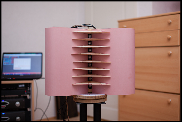
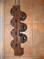
I built a prototype of a line array segment. I developed a waveguide to avoid the bad horizontal directivity of Keele's CBT line arrays.
I used 1" fullrange drivers (Aurasound NSW1-205-8A) which should be used above 300 Hz. The woofer section was not part of the study. The concept I have in mind consists of a 1m long line with woofers beneath and above. This should expand the narrow vertical directivity. CBT-like shading (amplitude and delay) works quite well even with only 7 drivers and symmetry around the driver in the middle.
The paper is in german only. But I think the measurements speak for themselves.")
Line array prototype with waveguide and shading (german)
Prototype with 8 drivers (36 cm high):
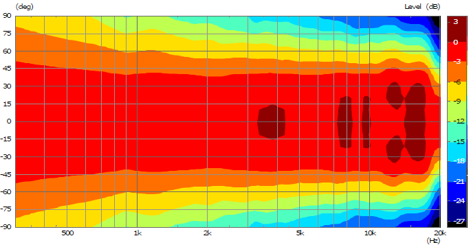
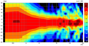
Horizontal directivity:
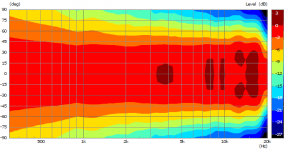
Vertical directivity (with truncated CBT9 shading):

The vertical horns dramatically reduce lobing above 9 kHz as you can see in the paper. In professional designs like the Seeburg GL 16 this is a standard feature.
When there is further progress I will let you know.
I used 1" fullrange drivers (Aurasound NSW1-205-8A) which should be used above 300 Hz. The woofer section was not part of the study. The concept I have in mind consists of a 1m long line with woofers beneath and above. This should expand the narrow vertical directivity. CBT-like shading (amplitude and delay) works quite well even with only 7 drivers and symmetry around the driver in the middle.
The paper is in german only. But I think the measurements speak for themselves.
Line array prototype with waveguide and shading (german)
Prototype with 8 drivers (36 cm high):
Horizontal directivity:
Vertical directivity (with truncated CBT9 shading):
The vertical horns dramatically reduce lobing above 9 kHz as you can see in the paper. In professional designs like the Seeburg GL 16 this is a standard feature.
When there is further progress I will let you know.
Attachments
Those polars are not-normalized.
This is not correct. They are normalized to 0°.
Do you use dsp or similar for EQ and xo?
Yes, I use a digital 3-way crossover from ALTO Pro Audio to apply the shading, delays, equalizing etc.
How is low end distortion - where to cross to subwoofer?
There are distortion measurements in the PDF file at 90 dB and 100 dB. THD is pretty low above about 300 Hz. So I would not set the crossover point below that. In this case calling the second way a "subwoofer" is not quite applicable.
Interesting project! Your assumption is wrong though in claiming the CBT designs proposed by Don Keele are "bad" in controlling horizontal directivity. This is usually assumed because it doesn't follow the common model.
In real use though (and I have heard and also designed / built several CBT arrays) I have found the horizontal coverage to work very well. In both home and pro audio I have not noticed any issues; in fact, the intelligibility of the pro audio systems has been excellent. If the horizontal directivity was an issue that area would be heavily affected. The ground plane CBT speakers also have greater control into the lower frequencies; as a result, the room interface is very good and they certainly outperform conventional designs in this respect.
In real use though (and I have heard and also designed / built several CBT arrays) I have found the horizontal coverage to work very well. In both home and pro audio I have not noticed any issues; in fact, the intelligibility of the pro audio systems has been excellent. If the horizontal directivity was an issue that area would be heavily affected. The ground plane CBT speakers also have greater control into the lower frequencies; as a result, the room interface is very good and they certainly outperform conventional designs in this respect.
"I developed a waveguide to avoid the bad horizontal directivity of Keele's CBT line arrays."
Can you explain what is bad about CBT horizontal directivity?
Please see this and scroll down for CBT...
Constant directivity loudspeaker designs
Can you explain what is bad about CBT horizontal directivity?
Please see this and scroll down for CBT...
Constant directivity loudspeaker designs
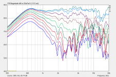
Here comes the requested diagram. The frequency response at 0° was equalized roughly.
This looks to me lot worse than original CBT...
Interesting project! Your assumption is wrong though in claiming the CBT designs proposed by Don Keele are "bad" in controlling horizontal directivity. This is usually assumed because it doesn't follow the common model.
What do you mean with "common model"?
The horizontal directivity can be considered independantly from the vertical. Aligning the drivers horizontally like Keele does leads to interferences, because the steepness of the crossover slope is not infinitely high.
In real use though (and I have heard and also designed / built several CBT arrays) I have found the horizontal coverage to work very well.
Do you have measurements of the horizontal directivity of Keele's designs?
The ground plane CBT speakers also have greater control into the lower frequencies; as a result, the room interface is very good and they certainly outperform conventional designs in this respect.
Yes, I believe this.
Can you explain what is bad about CBT horizontal directivity?
The horizontal directivity of Keele's designs is very broad up to 3 kHz (nearly half space). Above that the directivity gets more and more narrow.
Maybe the word "bad" was a bit to hard. It is ok, but not controlled. It seems to me that he focused only on vertical directivity, but neglected the horizontal a bit. With a waveguide it can be controlled to make it narrower and more constant.
This looks to me lot worse than original CBT...
Do you have similar measurements (1/12 oct) of Keele's design?
Of course it looks better vertically, because it has smaller tweeters and smaller distances between them. And my prototyp has only 7 active drivers and symmetrical shading. His designs have much more drivers and only half shading.
Examining the vertical directivity was not the goal of my prototype, because this can be easily improved by extending the line with more drivers. I was interested in the horizontal directivity.
I meant that the horizontal response curves that you're wanting to achieve is the common model of constant directivity. There's the assumption that anything different from that is inferior. In some cases that certainly may be true (such as horns with bad polar patterns or poor driver combinations).
True, there is some horizontal interference with the lines being side-by-side but this can be minimized with proper driver selection and crossover points /slopes. I use 96db slopes with my DEQX and it works well for me.
The CBT-36 that Don and Marshall designed for Audio Artistry uses tightly spaced small drivers with a low crossover point to give more of an omnidirectional pattern. There are horizontal measurements for it on the Audio Artistry website.
The horizontal coverage is more like an oval shape with uniform spectral content so there is more pattern control than one might think. I have horizontal curves for the passive crossover I did for the Gamechanger. When I get a chance I'll go back and run curves using the DEQX.
I meant that the horizontal response curves that you're wanting to achieve is the common model of constant directivity. There's the assumption that anything different from that is inferior. In some cases that certainly may be true (such as horns with bad polar patterns or poor driver combinations).
Ok, I got the point.
Yes, there are not only horns/waveguide to control the directivity. I used the "simple way" a couple of years ago. I built a 3-way speaker with 8", 2" and 0.5" drivers. I used low crossover points which leads to a very wide, but uniform directivity. This is the same concept which Keele uses horizontally.
For my speakers it worked fine in nearfield. And even fine if you walk around in the room and doing other things. But the reflections were much too strong. Imaging was bad at higher distance etc.
For my home theater I build 3-way speakers with dual waveguide. The waveguides were developed by a friend of mine and I had the luck to use them. They sound much better to my ears and work better with larger distances.
Documentation of HKL-01
Documentation of SBA-01

True, there is some horizontal interference with the lines being side-by-side but this can be minimized with proper driver selection and crossover points /slopes. I use 96db slopes with my DEQX and it works well for me.
I did it the same way in the past.
There are horizontal measurements for it on the Audio Artistry website.
I guess you mean from this document.

If this curves would be converted to a directivity sonogram it would not look very good. There is distinct narrowing at 1 kHz and 3 kHz.
Of course measurements with different setups (placing, windowing etc.) are not easy to compare. And the type of diagram, scaling and formatting can be very misleading. It would be interesting to get the raw files of those measurements. Then I could build sonograms with VACS for direct comparison.
I considered very long how to controll the horizontal directivity of a line array with two or more ways without placing the drivers side-by-side. This is is not an easy task. I had two options in mind:
- Developing a waveguide with small holes and placing the midrange driver behind that waveguide. This was done in the Seeburg GL16. The drawback is that it is a very complex thing to design. The holes act as helmholtz resonators and have to be tuned right. On the other side they are "invisible" for the tweeters.
- Settings the crossover point to a large wavelength (a few hundred Hz) and putting a small fullrange driver into a waveguide. The fullrange driver should cover most of the frequency range and can be very small to get a good coupling and wide horizontal dispersion in the highs.
I decided to try the second option. It is much easier to design.
And btw, I don't have the same goal as Keele. I want a narrow horizontal and vertical directivity. Keele's arcs and shading are designed to produce a rather wide directivity. The shading I experimented with was calculated for an angle of 80°. This is narrower than Keele's (120°).
And please don't get me wrong. Keele did great work with his line arrays and shading. His papers are just awsome! But the horizontal directivity can be better.
Last edited:
Interesting work and clearly a nice result from your line array. Can you better explain the benefit of your directivity vanes? Why do they work?
Keele's lateral response is a fairly minor compromise for the uniform frontal response provided. It is a function of the line arc. In the typical straight line array there is no horizontal effect from a line, the horizontal directivity is identical to that of a single element. With the array in an arc, you have added a depth dimension and the horizontal polars will show some interference effect.
Note that in the straight line implementation you have used (with electrical delay rather than physical delay) the issue is side stepped because the elements are always "recessed" away from the listener, no matter what the observation angle.
Regards,
David
Interesting work and clearly a nice result from your line array. Can you better explain the benefit of your directivity vanes? Why do they work?
Do you mean the wooden splines? Sorry, I don't know the correct technical term for this.
The vertical interferences (lobes) are caused by the distance of 4 cm between the driver's centers. Each driver radiates spherical up to a certain frequency which is not ideal for a line array. Now the trick is to narrow the vertical directivity of each driver. This means that under larger angles there is much less sound pressure which can interfere. The vanes act as small horns which narrows the directivity only in the highs.
Note that in the straight line implementation you have used (with electrical delay rather than physical delay) the issue is side stepped because the elements are always "recessed" away from the listener, no matter what the observation angle.
Yes, that's true. Beside that it is much cheaper and easier to build. The waveguide was milled out of some kind of plastic. With curving it would be much more expensive (I already payed 320 € for the current waveguide). And using digital delays has the advantage to "tune" the directivity. On the other side much more electronic components have to be used (even with stepped shading). So it may be not much less expensive.
To illustrate the effect of the vanes a bit better I simulated the 1" driver with AxiDriver in an infinite baffle.
Driver only:

Driver with very narrow horn:

Please take a look at the marked areas. These are the places where the strong lobes occur. Without vanes there is about -10 dB of sound pressure which interferes with the othe drivers. With vanes there is only -20 dB. This is the reason why vanes improve the lobing dramatically.
Driver only:
Driver with very narrow horn:
Please take a look at the marked areas. These are the places where the strong lobes occur. Without vanes there is about -10 dB of sound pressure which interferes with the othe drivers. With vanes there is only -20 dB. This is the reason why vanes improve the lobing dramatically.
I decided to try the second option. It is much easier to design.
And btw, I don't have the same goal as Keele. I want a narrow horizontal and vertical directivity. Keele's arcs and shading are designed to produce a rather wide directivity. The shading I experimented with was calculated for an angle of 80°. This is narrower than Keele's (120°).
And please don't get me wrong. Keele did great work with his line arrays and shading. His papers are just awsome! But the horizontal directivity can be better.[/QUOTE]
No problem - I don't want to take anything away from what you're doing either. Your approach is very thorough. True, Don's focus was more on the vertical response behavior. That's one reason why the particular tweeter was used for the CBT-36 because he wanted a low crossover point and close driver spacing. Cost was also an issue and they wanted to keep the price reasonable for DIY builders.
The curves you posted were taken with a 1K crossover point and (if I remember correctly) 96db slopes. The dip at 1K is expected because of the delay changing as you move off-axis. The off-axis response at 3K is probably more a result of driver behavior than the CBT design. When we had the CBT-36 at the RMAF show I raised the crossover point and I think it improved the sound quite a bit.
I do like the simplified enclosure of a straight array with active shading and delays but as you mentioned this also increases the cost and complexity of the electronics. One concern Don mentioned was being able to apply the an accurate amount of delay if going active.
And btw, I don't have the same goal as Keele. I want a narrow horizontal and vertical directivity. Keele's arcs and shading are designed to produce a rather wide directivity. The shading I experimented with was calculated for an angle of 80°. This is narrower than Keele's (120°).
And please don't get me wrong. Keele did great work with his line arrays and shading. His papers are just awsome! But the horizontal directivity can be better.
[/QUOTE]No problem - I don't want to take anything away from what you're doing either. Your approach is very thorough. True, Don's focus was more on the vertical response behavior. That's one reason why the particular tweeter was used for the CBT-36 because he wanted a low crossover point and close driver spacing. Cost was also an issue and they wanted to keep the price reasonable for DIY builders.
The curves you posted were taken with a 1K crossover point and (if I remember correctly) 96db slopes. The dip at 1K is expected because of the delay changing as you move off-axis. The off-axis response at 3K is probably more a result of driver behavior than the CBT design. When we had the CBT-36 at the RMAF show I raised the crossover point and I think it improved the sound quite a bit.
I do like the simplified enclosure of a straight array with active shading and delays but as you mentioned this also increases the cost and complexity of the electronics. One concern Don mentioned was being able to apply the an accurate amount of delay if going active.
The curves you posted were taken with a 1K crossover point and (if I remember correctly) 96db slopes. The dip at 1K is expected because of the delay changing as you move off-axis. The off-axis response at 3K is probably more a result of driver behavior than the CBT design.
I guess the dip at 3 kHz are from diffractions, because of the small baffle. Or reflections on the midrange driver. I simulated a lot with different waveguides and baffles and the geometry (width, round edges etc.) has a great influence of the lateral response.
I do like the simplified enclosure of a straight array with active shading and delays but as you mentioned this also increases the cost and complexity of the electronics. One concern Don mentioned was being able to apply the an accurate amount of delay if going active.
This is a problem, indeed. Common audio processors support only delays of a multiple of 1/fs. This means steps of 21 ms for 48 kHz sampling frequency.
But there is a solution.
Acourate can do inter-sample delays. Then a convolver is necessary (PC-based or standalone).
- Home
- Loudspeakers
- Multi-Way
- Line array prototype (with waveguide and CBT shading)