I'm trying to work on a crossover for a 2 way speaker using a HiVi D5G and Dayton RS28F-4 (unless anyone else has any suggestions for a tweeter that can x-over low with a similar price point. Might be a good idea, impedance gets pretty low on it) and I'm using Jeff Bagby's excel sheets. However when using the FRD/ZMA files that have been run through Response Modeller the impedance and impedance phase seem to be hard to believe. I suspect I'm doing something wrong, since when I use the normal, unaltered files it looks much more normal.
If you need any other pics/info just ask
If you need any other pics/info just ask
Attachments
Use frd's and zma's of the drivers installed in the box of your interest
and then simulate it using PCD. Phase issue is another way of saying
there is something wrong with the FR. Concentrate on getting FR right
in the XO range. Use filter orders which give you smooth transition.
Attach all data you have, someone might help you.
and then simulate it using PCD. Phase issue is another way of saying
there is something wrong with the FR. Concentrate on getting FR right
in the XO range. Use filter orders which give you smooth transition.
Attach all data you have, someone might help you.
Use frd's and zma's of the drivers installed in the box of your interest
and then simulate it using PCD. Phase issue is another way of saying
there is something wrong with the FR. Concentrate on getting FR right
in the XO range. Use filter orders which give you smooth transition.
Attach all data you have, someone might help you.
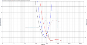
I think I have worked out what is happening. RM isn't modifying the ZMA files correctly. If I import a modified ZMA into PCD, it's completely wacky, the raw impedance curve doesn't even show up so whatever is in the main impedance window is from the crossover, not including the driver. If I switch out the ZMA for the unmodified version it looks much more normal, both for driver impedance and imp. phase angle. However this won't give an accurate design since it won't include the box effects on impedance... Although it's effects are, for the most part, nowhere near the crossover freq.
As you can see in the attached images, it only shows the imported impedance plot, and doesn't show anything for the modified plot involving the box (which shows up fine with the box design in various box design software)
Also the phase of including the box...
Should I just plot a ZMA from an image of the impedance plot from bassbox/unibox and ignore running it through RM? Or is there something in RM I am missing that is causing this issue?

Attachments
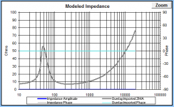
Personally, I almost always simulate the impedance of woofers in response modeler and never go through the trouble of tracing it beforehand. Then when you start to play with box alignment the effects on impedance will show right up. It's not perfect but it saves time and trouble and has proved effective for me. I just fiddle with it until the curve looks comparable to the actual measured curve.Should I just plot a ZMA from an image of the impedance plot from bassbox/unibox and ignore running it through RM? Or is there something in RM I am missing that is causing this issue?
But maybe you're doing things in the wrong order? I start with the unmodified traced spl, work out the impedance using T/S parameters and whatever box I want to use, splice the box plot onto the SPL plot, then add in baffle effects, either from the bottom of Response Modeler or with the separate Boundary&Diffraction simulator. Doing it this way yields good results for me.
I am not familiar with the ZMA files generated by Response Modeller but have a look at the generated ZMA file using a text processor like Notepad.
Delete any information other than the impedance data (like headers etc), save it under a new name and try importing the modified file.
Delete any information other than the impedance data (like headers etc), save it under a new name and try importing the modified file.
If the published impedance curves could be trusted, it might be possible to design a passive crossover somewhat properly. If they are off by one ohm, the actual crossover point could move enough to cause a very different phase relationship between the woofer and tweeter at the crossover frequency. this could cause a big "suckout" or larger crossover region projection damage. I have found that it's a good idea to measure each driver independently after I get the whole thing built with the preliminary crossover in place, to see where in frequency each driver is actually rolling off, and then either swap the phase of one driver so they add better at the crossover freq., or readjust the cap or coil size. It's probable that you will want to do more calibrating of the crossover when you see the results.
Response Modeler
Jim,
I've used RS 28F-4's TS parameters Fs, Qes, Qms and Vas, selected sealed box
(tweeter) and toggled the Le Expon to make it look like a real impedance measurement.
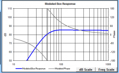
The same principle for making a frd of it. Just for illustration purpose.
Import them to PCD and it should work.
Change the .txt extension to .frd for Fr and .zma for IMP.
Jim,
I've used RS 28F-4's TS parameters Fs, Qes, Qms and Vas, selected sealed box
(tweeter) and toggled the Le Expon to make it look like a real impedance measurement.
The same principle for making a frd of it. Just for illustration purpose.
Import them to PCD and it should work.
Change the .txt extension to .frd for Fr and .zma for IMP.
Attachments
- Status
- This old topic is closed. If you want to reopen this topic, contact a moderator using the "Report Post" button.
- Home
- Loudspeakers
- Multi-Way
- Impedance phase issues and tweeter choice