Hello folks,
I am trying to fix via mechanical means a peak-dip feature I have in some speakers I am putting together. It is the based on the Nautaloss speakers made by xrk. This post is gonna be long, so bear with me here...
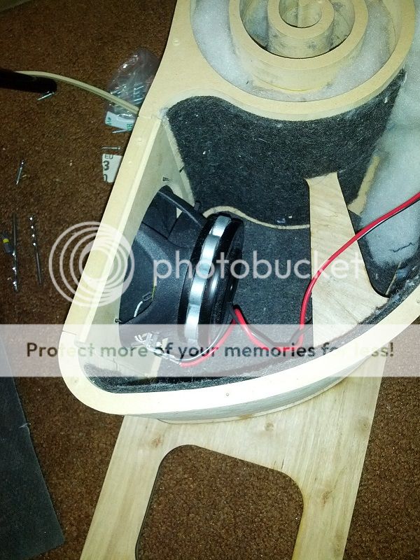
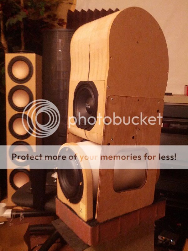
This is what my speaker actually looks like:
This is what the freq response is supposed to look like, from the manufacturer:
It's a 5" full range driver from PRV
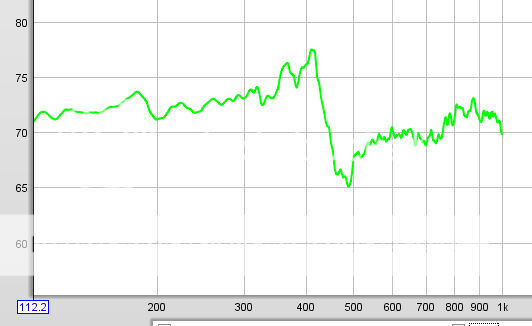
Here is the freq response when I put it in the box, with the mic very close (6")
Not including the high freq spray (I will address that some other day), there is a big fat hole right around 1.6 kHz.
I have seen something like this before, also in a measurement of my Martin Logan's woofer, in its default cabinet, XO circuit disabled.
I figure this must be some kind of mechanical resonance thingie, where there is a peak-dip, and lowered response afterwards. (Incidentally, it is just begging to be fixed with a high Q high shelf filter, LOL).
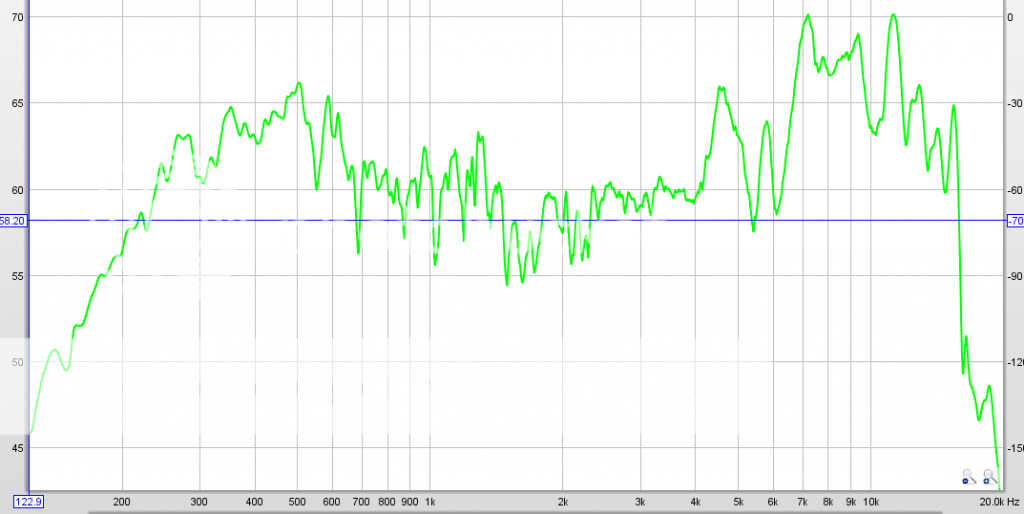
Next, I took my driver and put it in an open baffle, since that is supposed to be some standard way to measure drivers. The dip is less severe, maybe only 5 db, but still at the exact same freq. The mic is further away, so there is more noise in the measurement
Making the case wider or narrower made no difference at all.
(thus I figure this doesn't have anything to do with reflections between the parallel side walls)
Mounting the driver with a foam gasket and weakly coupled screws also made no difference.
Adding stuffing to the front of the case near the driver made very little difference.
Things that do make a difference:
-putting some blobs of clay on the cone. This can significantly reduce the dip, at the expense of creating lower frequency dips and peaks.
-VERY densely stuffing polyfill INSIDE the driver's spider, right against the back side of the cone. Reduces the dip by a little, and shifts it frequency up.
-adding a short slice of a cone / tube against the back side of the driver to "redirect" the backwave "back" instead of "sideways and outwards". This seems to make its own peak-dip perturbation, but I think if you make the length just right it can help cancel.
This is the best I was able to do so far:
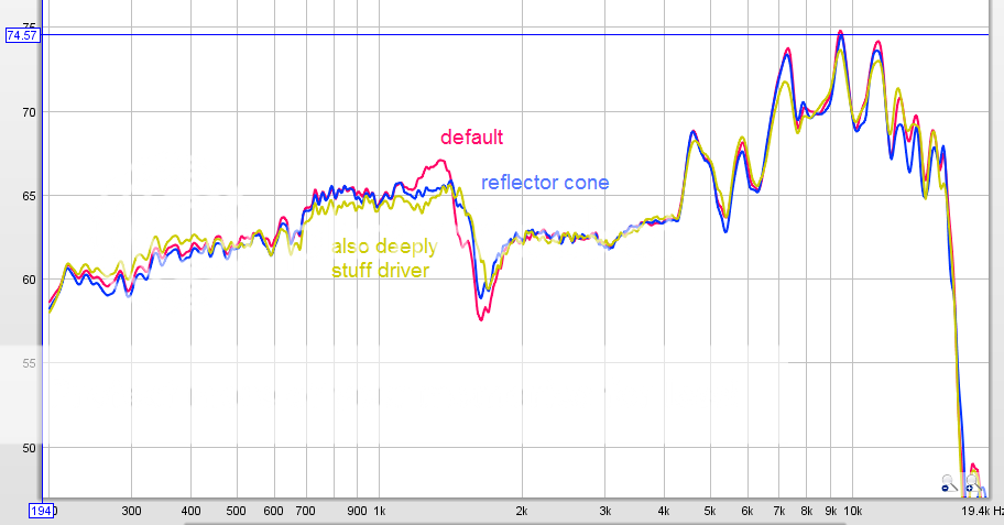
red - default as measured in box
blue - add that little cone on the backside of driver
yellow - also add stuffing INSIDE driver
If you look carefully, you might think that there are actually two or more dips caused (perhaps from difference effects) by putting the speaker in this box, which just happen to coincide at the almost the same freq.
In the end, I am trying to figure out what is the cause of this dip and how to fix it.
I am trying to fix via mechanical means a peak-dip feature I have in some speakers I am putting together. It is the based on the Nautaloss speakers made by xrk. This post is gonna be long, so bear with me here...
This is what my speaker actually looks like:
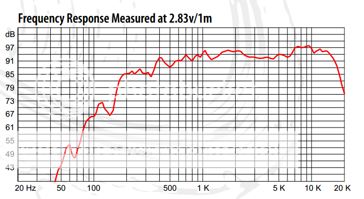
This is what the freq response is supposed to look like, from the manufacturer:
It's a 5" full range driver from PRV
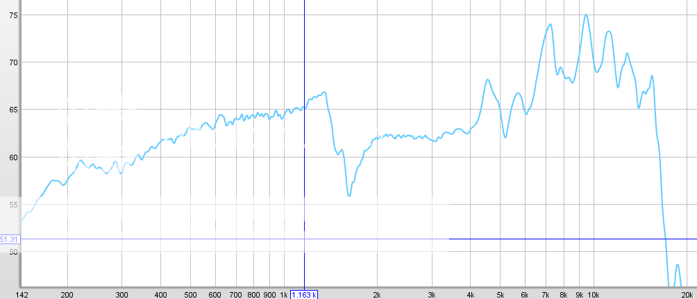
Here is the freq response when I put it in the box, with the mic very close (6")
Not including the high freq spray (I will address that some other day), there is a big fat hole right around 1.6 kHz.
I have seen something like this before, also in a measurement of my Martin Logan's woofer, in its default cabinet, XO circuit disabled.
I figure this must be some kind of mechanical resonance thingie, where there is a peak-dip, and lowered response afterwards. (Incidentally, it is just begging to be fixed with a high Q high shelf filter, LOL).
Next, I took my driver and put it in an open baffle, since that is supposed to be some standard way to measure drivers. The dip is less severe, maybe only 5 db, but still at the exact same freq. The mic is further away, so there is more noise in the measurement
Making the case wider or narrower made no difference at all.
(thus I figure this doesn't have anything to do with reflections between the parallel side walls)
Mounting the driver with a foam gasket and weakly coupled screws also made no difference.
Adding stuffing to the front of the case near the driver made very little difference.
Things that do make a difference:
-putting some blobs of clay on the cone. This can significantly reduce the dip, at the expense of creating lower frequency dips and peaks.
-VERY densely stuffing polyfill INSIDE the driver's spider, right against the back side of the cone. Reduces the dip by a little, and shifts it frequency up.
-adding a short slice of a cone / tube against the back side of the driver to "redirect" the backwave "back" instead of "sideways and outwards". This seems to make its own peak-dip perturbation, but I think if you make the length just right it can help cancel.
This is the best I was able to do so far:
red - default as measured in box
blue - add that little cone on the backside of driver
yellow - also add stuffing INSIDE driver
If you look carefully, you might think that there are actually two or more dips caused (perhaps from difference effects) by putting the speaker in this box, which just happen to coincide at the almost the same freq.
In the end, I am trying to figure out what is the cause of this dip and how to fix it.
Last edited:
It could be the standing wave of the lateral/width dimension of the chamber right behind the baffle. Is also vertical dimension same as horizontal right at spider level? Chamber stuffing seems to alleviate it...
What is your measuring distance? If this is happenig outside the box, it does not show up at just an inch from the membrane.
xrk has some interesting designs, but they carry lots of caveats acoustically.
What is your measuring distance? If this is happenig outside the box, it does not show up at just an inch from the membrane.
xrk has some interesting designs, but they carry lots of caveats acoustically.
Last edited:
That is a very odd feature. 1.6kHz is 4.2 inches half wave distance. Look for that distance between your cone membrane and a hard surface. Add lots of foam or felt to cover that surface. My boxes are made of softer foam core and I wonder if that helps to prevent hard surface reflections? I also line the inside of the flat front baffle where the cutout is with grey open cell foam.
While I'm not arguing anything about the cause of your problem, I must say that the right measurement method is gated far field, so mic at least 50 cm (20") away from the driver. For anything under 200-300Hz use near field instead (not gated, 0.5 cm distance).
Measure again.
Ralf
Measure again.
Ralf
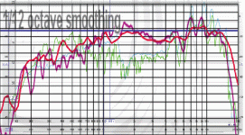
This is PRV 5MR450-NDY, right? It is true that xrk971's measurements (purple) resemble the spec sheet (red), and these (green, blue) don't...
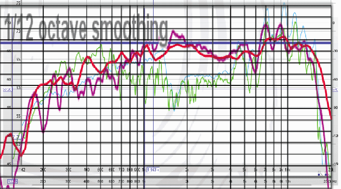
I agree, and post the impulse too, zoomed in on the first ~8 ms.I must say that the right measurement method is gated far field, so mic at least 50 cm (20") away from the driver. For anything under 200-300Hz use near field instead (not gated, 0.5 cm distance).
Measure again.
Attachments
1) measure with far higher integration (at least 1/3 octave , even 1/2 octave) to damp the "fuzzies" and achieve a curve closer to that published by the speaker maker.
Otherwise excess of detail clouds the issue instead of clearing it.
2) I design and make guitar speakers and I see that 1.5kHz anomaly all day long, just look at any guitar speaker curve and you'll see it too.
And being a phase cancellation is impossible to equalize.
In your case, it *might* be caused by speaker cabinet (or front panel) diffraction, so my first suggestion would be to pull the speaker from any "fancy" enclosure, simply to reduce the number of variables, and mount it in a large flat panel, which is the simplest baffle there is (and the easiest to duplicate") )
)
You seem to have done something like that, yet that anomaly didn't change (much) , so I suspect the second culprit (the one I always find in guitar speakers) which is undamped/uncontrolled cone flexing.
xrk971 (correctly) says:
So at certain frequencies, center and edge may (and do) move out of phase and produce impossible to equalize dips .
Standard solution is to properly damp edge, so there's no out of phase backwave reflected from the edge travelling back to the VC/cone center and messing things up.
One non standard solution is to apply mass at random points (what you did applying clay) to break that backwave. Sounds like a desperate solution to me.
3) so I must also agree that, since other speakers same brand and model do not show that behaviour, it's a speaker defect and you will not correct it with cabinet alterations.
I'd speak to the speaker manufacturer and tell him about it, showing measurements and even pointing to this thread.
He might have had a bad cone batch or simply yours was improperly assembled.
I guess he will exchange a new one and get the bad one to see what problem happened.
I know I would.
Otherwise excess of detail clouds the issue instead of clearing it.
2) I design and make guitar speakers and I see that 1.5kHz anomaly all day long, just look at any guitar speaker curve and you'll see it too.
And being a phase cancellation is impossible to equalize.
In your case, it *might* be caused by speaker cabinet (or front panel) diffraction, so my first suggestion would be to pull the speaker from any "fancy" enclosure, simply to reduce the number of variables, and mount it in a large flat panel, which is the simplest baffle there is (and the easiest to duplicate
)You seem to have done something like that, yet that anomaly didn't change (much) , so I suspect the second culprit (the one I always find in guitar speakers) which is undamped/uncontrolled cone flexing.
xrk971 (correctly) says:
and that is true for sound moving through air, of course no part of a 5" speaker is 4.2" away from the voice coil, but cone does not move as a rigid piston (even less at 1.6kHz) and that flexion wave moves from center to edge at a different (lower) speed than speed of sound in air, the same way that a sea wave moves at a far slower speed than speed of sound in water.1.6kHz is 4.2 inches half wave distance. Look for that distance between your cone membrane and a hard surface.
So at certain frequencies, center and edge may (and do) move out of phase and produce impossible to equalize dips .
Standard solution is to properly damp edge, so there's no out of phase backwave reflected from the edge travelling back to the VC/cone center and messing things up.
One non standard solution is to apply mass at random points (what you did applying clay) to break that backwave. Sounds like a desperate solution to me.
3) so I must also agree that, since other speakers same brand and model do not show that behaviour, it's a speaker defect and you will not correct it with cabinet alterations.
I'd speak to the speaker manufacturer and tell him about it, showing measurements and even pointing to this thread.
He might have had a bad cone batch or simply yours was improperly assembled.
I guess he will exchange a new one and get the bad one to see what problem happened.
I know I would.
You're measuring WAY too close to measure anything meaningful as high as 1.6Khz.Hello folks,
Here is the freq response when I put it in the box, with the mic very close (6")
Not including the high freq spray (I will address that some other day), there is a big fat hole right around 1.6 kHz.
The generally accepted maximum frequency for near field measurement is no more than 300Hz depending on the size of the driver. 6" is not near field but it is not far field either, it's in a transition region between the two where you will not get useful measurements at the frequencies of interest.
It's important to understand that a high frequency measurement made in the nearfield is always invalid.
For example, even if you had a 5" driver that was an ideal flat piston and measured perfectly flat in response at a distance the near field response would be anything but flat - and there would definitely be very large peaks and dips in the response above 1Khz or so. I've measured it myself many times.
For a technical explanation of why, section two of the following ARTA application notes paper is very good:
http://www.artalabs.hr/AppNotes/AP4_FreeField-Rev03eng.pdf
In more lay terms it can be explained by geometry - when the listening point approaches infinity distance away from the speaker all of the points on a theoretical flat piston sum together in phase at all frequencies.
However as you approach the piston closer and closer a distance differential starts to occur between some points of the piston and and others to the listener - as you get near the middle you're now closer to the middle of the cone than you are to the edge so they no longer sum in phase and cancellation starts to occur since the final result is the sum of an infinite number of points across the surface. This results in deep notches and peaks that move in frequency in a kind of ripple fashion as you get closer.
To see the effect in action it's useful to enable a noise based realtime RTA mode if your software has it, then watch the response as you move the microphone from a metre away gradually towards the centre of the cone.
To get a valid response at high frequencies you must be at least 3 times the diameter of the driver away from the cone, so for a 5" cone 15" at the absolute minimum. On a real cabinet you'll get diffraction from the cabinet edges - this artificially increases the "apparent size" of the acoustic source at some frequencies, so in practice you need to be at least 3x the width of the cabinet away - so if you have a cabinet that's 15" wide you need to be 45" away, minimum! 6" simply won't cut it and will just mislead you.
Assuming that's an un-gated measurement it's not "noise" in the measurement, it's room reflections being summed into the response. This too will only mislead you. You really can't read too much into that measurement.Next, I took my driver and put it in an open baffle, since that is supposed to be some standard way to measure drivers. The dip is less severe, maybe only 5 db, but still at the exact same freq. The mic is further away, so there is more noise in the measurement
What you need for high frequencies is a reflection free gated measurement taken at sufficient distance - the more time delay you can arrange between the direct path to the microphone and the first reflection the better result you'll get. This usually means putting the speaker up on a stand in the middle of the room at about half the floor/ceiling height with the microphone about 1-1.5 metres away.
If the microphone is too close you get inaccuracies in the response for the reasons I described earlier, (especially with large speakers) while if you get too far away you reduce the time delay to the first reflection causing you to have to set a shorter gate time and lose low frequency accuracy. Unless you have a warehouse or a large room with a high ceiling to work with it's definitely a juggling act to get a compromise between the two.
I'm not saying that measurement problems are the whole issue and that there isn't something wrong with the driver or speaker, but you're never going to know until you are making measurements that actually mean something. If you follow best practices for measurement technique and there is still a significant anomaly at 1.6Khz then at least an accurate measurement technique will make it possible to find the cause.
Last edited:
Yep. With the mic 1m away and the speaker 1m away from the nearest boundary, he should be able to get some fairly accurate measurements down to almost 1kHz.You're measuring WAY too close to measure anything meaningful as high as 1.6Khz.
I had a similar issue with my morel MW-144's (also 5") although my dip was around 2Khz. In the end I decided it was an unfortunate combination of the driver, box dimentions, baffle diffraction and probably a number of other things, that I wasn't going to be able to deal with without a new box (and even then there was no guarantee because measurements of the driver in free air showed the same tendency).
I dealt with it as best I could with the crossover. The end result was slightly less efficient speakers but a good response, and they sound good.
Tony.
I dealt with it as best I could with the crossover. The end result was slightly less efficient speakers but a good response, and they sound good.
Tony.
This is what the freq response is supposed to look like, from the manufacturer:
It's a 5" full range driver from PRV
Interesting! Current measurement clearly shows the peak/dip: https://www.parts-express.com/pedocs/specs/294-2704--prv-audio-5mr450-ndy-4-specifications.pdf
Anyway, tack some polyfil on the dustcap to test, my SWAG is the high Q shaped surround's eigenmodes.
GM
See Klippel for definitive answer ...
Title: Measurement and Visualization of Loudspeaker Cone Vibration
Authors: Wolfgang Klippel and Joachim Schlechter
URL: https://www.klippel.de/fileadmin/kl...linearities_Causes,Parameters,Symptoms_06.pdf
… particularly Section 5 Interpretation. WHG
Title: Measurement and Visualization of Loudspeaker Cone Vibration
Authors: Wolfgang Klippel and Joachim Schlechter
URL: https://www.klippel.de/fileadmin/kl...linearities_Causes,Parameters,Symptoms_06.pdf
… particularly Section 5 Interpretation. WHG
- Status
- This old topic is closed. If you want to reopen this topic, contact a moderator using the "Report Post" button.
- Home
- Loudspeakers
- Multi-Way
- What causes this peak-dip in frequency response?